Tag: VASP tutorial

VASP tutor: Structure optimization through Equation-of-State fitting

Materials properties, such as the electronic structure, depend on the atomic structure of a material. For this reason it is important to optimize the atomic structure of the material you are investigating. Generally you want your system to be in the global ground state, which, for some systems, can be very hard to find. This can be due to large barriers between different conformers, making it easy to get stuck in a local minimum. However, a very shallow energy surface will be problematic as well, since optimization algorithms can get stuck wandering these plains forever, hopping between different local minima (Metal-Organic Frameworks (MOFs) and other porous materials like Covalent-Organic Frameworks and Zeolites are nice examples).

VASP, as well as other ab initio software, provides multiple settings and possibilities to perform structure optimization. Let’s give a small overview, which I also present in my general VASP introductory tutorial, in order of increasing workload on the user:

  1. Experimental Structure: This the most lazy option, as it entails just taking an experimentally obtained structure and not optimizing it at all. This should be avoided unless you have a very specific reason why you want to use specifically this geometry. (In this regard, Force-Field optimized structures fall into the same category.)
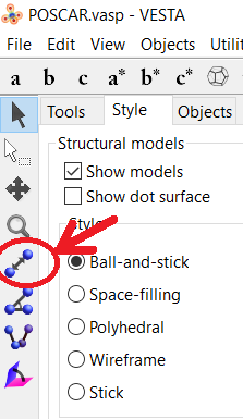
  2. Simple VASP Optimization: You can let VASP do the heavy lifting. There are several parameters which help with this task.
    1. IBRION = 1 (RMM-DIIS, good close to a minimum), 2 (conjugate gradient, safe for difficult problems, should always work), 3 (damped molecular dynamics, useful if you start from a bad initial guess) The IBRION tag determines how ions are moved during relaxation.
    2. ISIF = 2 (Ions only, fixed shape and volume), 4 (Ions and cell shape, fixed volume), 3 (ions, shape and volume relaxed) The ISIF tag determines how the stress tensor is calculated, and which degrees of freedom can change during a relaxation.
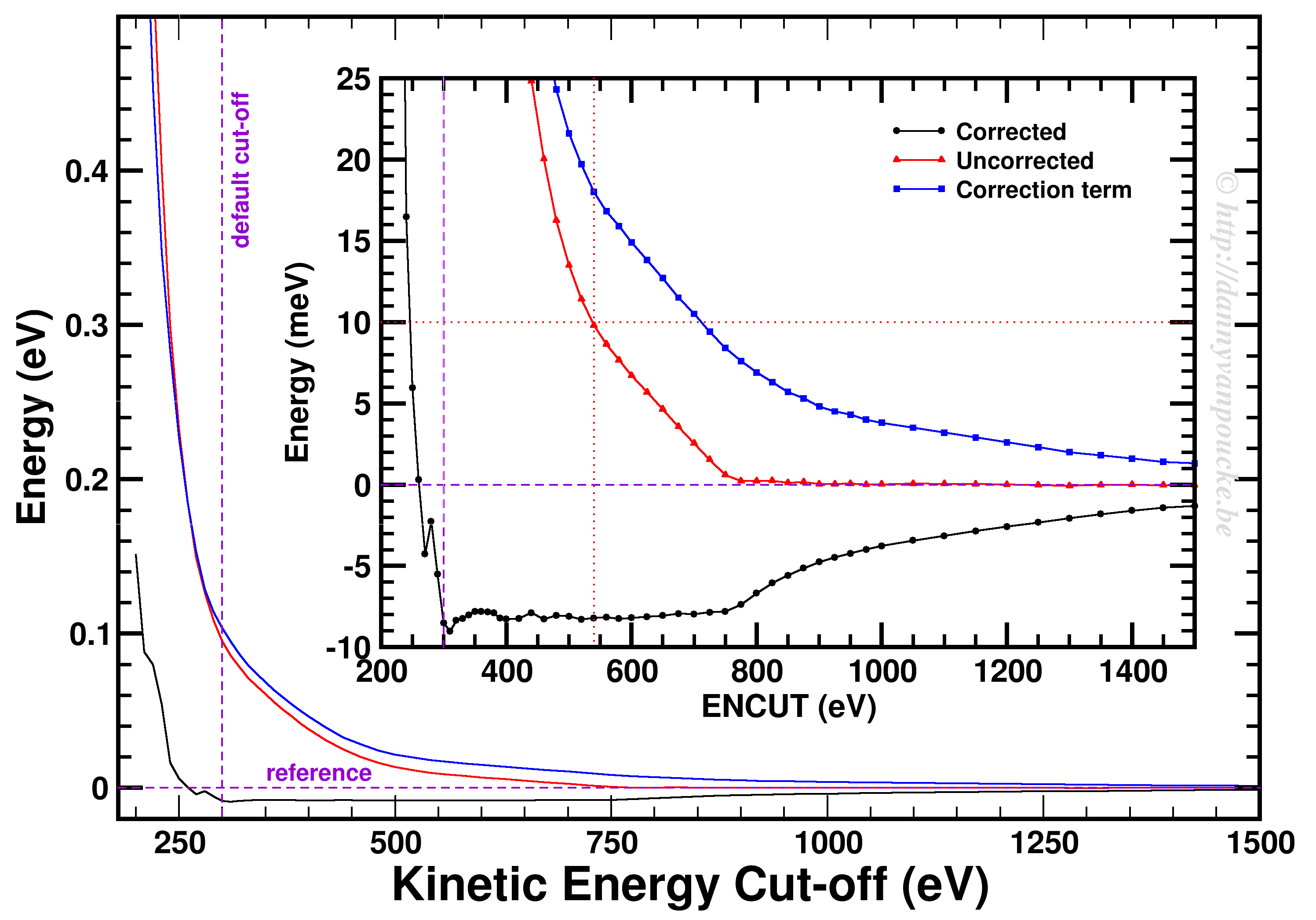
    3. ENCUT = max(ENMAX)x1.3  To reduce Pulay stresses, it is advised to increase the basis set to 1.3x the default value, which is the largest ENMAX value for the atoms used in your system.
  1. Volume Scan (Quick and dirty): For many systems, especially simple systems, the internal coordinates of the ions are often well represented in available structure files. The main parameter which needs optimization is the lattice parameter. This is also often the main change if different functional are used. In a quick and dirty volume scan, one performs a set of static calculations, only the volume of the cell is changed. The shape of the cell and the internal atom coordinates are kept fixed. Fitting a polynomial to the resulting Energy-Volume data can then be used to obtain the optimum volume. This option is mainly useful as an initial guess and should either be followed by option 2, or improved to option 4.
  2. Equation of state fitting to fixed volume optimized structures: This approach is the most accurate (and expensive) method. Because you make use of fixed volume optimizations (ISIF = 4), the errors due to Pulay stresses are removed. They are still present for each separate fixed volume calculation, but the equation of state fit will average out the basis-set incompleteness, as long as you take a large enough volume range: 5-10%. Note that the 5-10% volume range is generally true for small systems. In case of porous materials, like MOFs, ±4% can cover a large volume range of over 100 Å3. Below you can see a pseudo-code algorithm for this setup. Note that the relaxation part is split up in several consecutive relaxations. This is done to further reduce basis-set incompleteness errors. Although the cell volume does not change, the shape does, and the original sphere of G-vectors is transformed into an ellipse. At each restart this is corrected to again give a sphere of G-vectors. For many systems the effect may be very small, but this is not always the case, and it can be recognized as jumps in the energy going from one relaxation calculation to the next. The convergence is set the usual way for a relaxation in VASP (EDIFF and EDIFFG parameters) and a threshold in the number of ionic steps should be set as well (5-10 for normal systems is reasonable, while for porous/flexible materials you may prefer a higher value). There exist several possible equations-of-state which can be used for the fit of the E(V) data. The EOSfit option of HIVE-4 implements 3:
    1. Birch-Murnaghan third order isothermal equation of state
    2. Murnaghan equation of state
    3. Rose-Vinet equation of state (very well suited for (flexible) MOFs)

    Using the obtained equilibrium volume a final round of fixed volume relaxations should be done to get the fully optimized structure.

For (set of Volumes: equilibrium volume ±5%){
	Step 1          : Fixed Volume relaxation
	(IBRION = 2, ISIF=4, ENCUT = 1.3x ENMAX, LCHARG=.TRUE., NSW=100)
	Step 2→n-1: Second and following fixed Volume relaxation (until a threshold is crossed and the structure is relaxed in fewer than N ionic steps) (IBRION = 2, ISIF=4, ENCUT = 1.3x ENMAX, ICHARG=1, LCHARG=.TRUE., NSW=100) 
	Step n : Static calculation (IBRION = -1, no ISIF parameter, ICHARG=1, ENCUT = 1.3x ENMAX, ICHARG=1, LCHARG=.TRUE., NSW=0) 
} 
Fit Volume-Energy to Equation of State.
Fixed volume relaxation at equilibrium volume. (With continuations if too many ionic steps are required.) 
Static calculation at equilibrium volume
EOS-fitting Diamond and Graphite

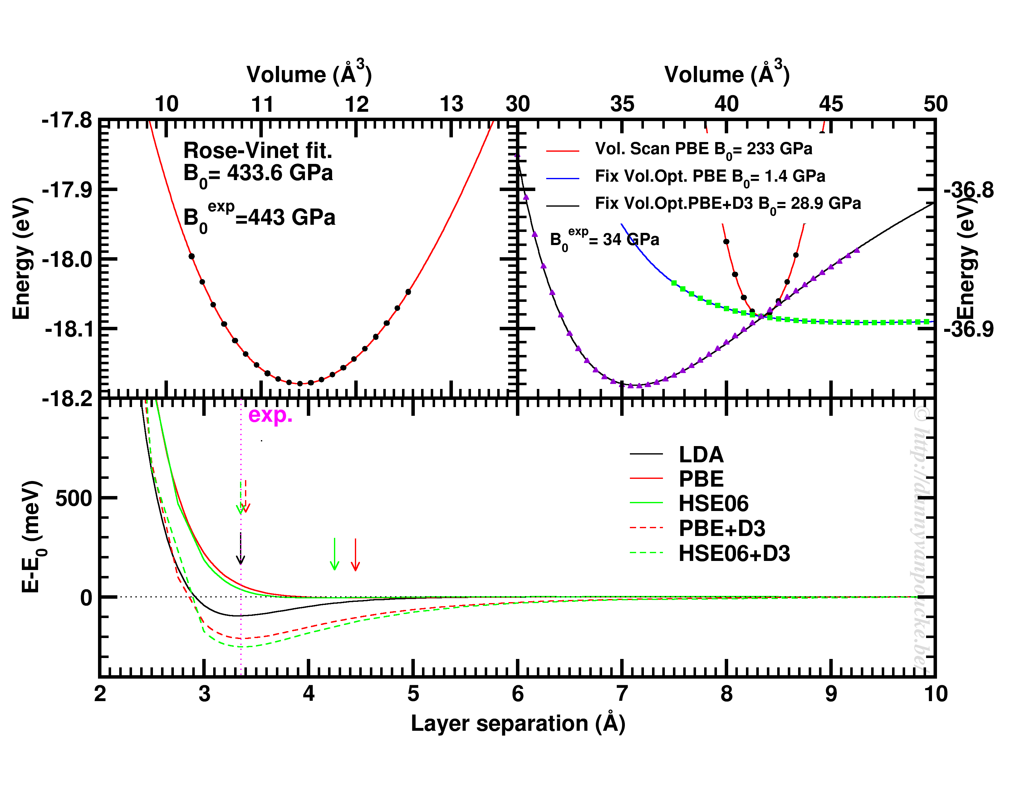
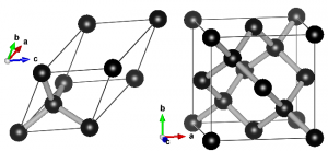
Top-left: Volume scan of Diamond. Top-right: comparison of volume scan and equation of state fitting to fixed volume optimizations, showing the role of van der Waals interactions. Bottom: Inter-layer binding in graphite for different functionals.

Some examples

Let us start with a simple and well behaved system: Diamond. This material has a very simple internal structure. As a result, the internal coordinates should not be expected to change with reasonable volume variations. As such, a simple volume scan (option 3), will allow for a good estimate of the equilibrium volume. The obtained bulk modulus is off by about 2% which is very good.

Switching to graphite, makes things a lot more interesting. A simple volume scan gives an equilibrium volume which is a serious overestimation of the experimental volume (which is about 35 Å3), mainly due to the overestimation of the c-axis. The bulk modulus is calculated to be 233 GPa a factor 7 too large. Allowing the structure to relax at fixed volume changes the picture dramatically. The bulk modulus drops by 2 orders of magnitude (now it is about 24x too small) and the equilibrium volume becomes even larger. We are facing a serious problem for this system. The origin lies in the van der Waals interactions. These weak forces are not included in standard DFT, as a result, the distance between the graphene sheets in graphite is gravely overestimated. Luckily several schemes exist to include these van der Waals forces, the Grimme D3 corrections are one of them. Including these the correct behavior of graphite can be predicted using an equation of state fit to fixed volume optimizations.(Note that the energy curve was shifted upward to make the data-point at 41 Å3 coincide with that of the other calculations.) In this case the equilibrium volume is correctly estimated to be about 35 Å3 and the bulk modulus is 28.9 GPa, a mere 15% off from the experimental one, which is near perfect compared to the standard DFT values we had before.

In case of graphite, the simple volume scan approach can also be used for something else. As this approach is well suited to check the behaviour of 1 single internal parameter, we use it to investigate the inter-layer interaction. Keeping the a and b lattice vectors fixed, the c-lattice vector is scanned. Interestingly the LDA functional, which is known to overbind, finds the experimental lattice spacing, while both PBE and HSE06 overestimate it significantly. Introducing D3 corrections for these functionals fixes the problem, and give a stronger binding than LDA.

EOS-fitting for MIL53-MOFs

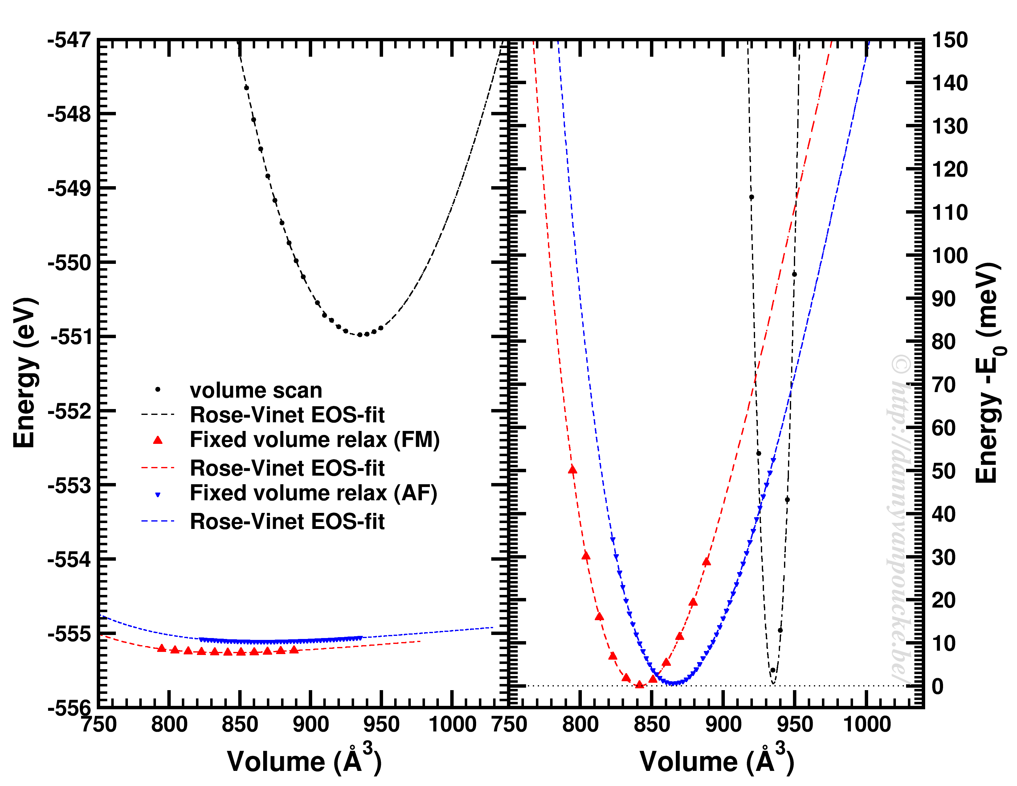
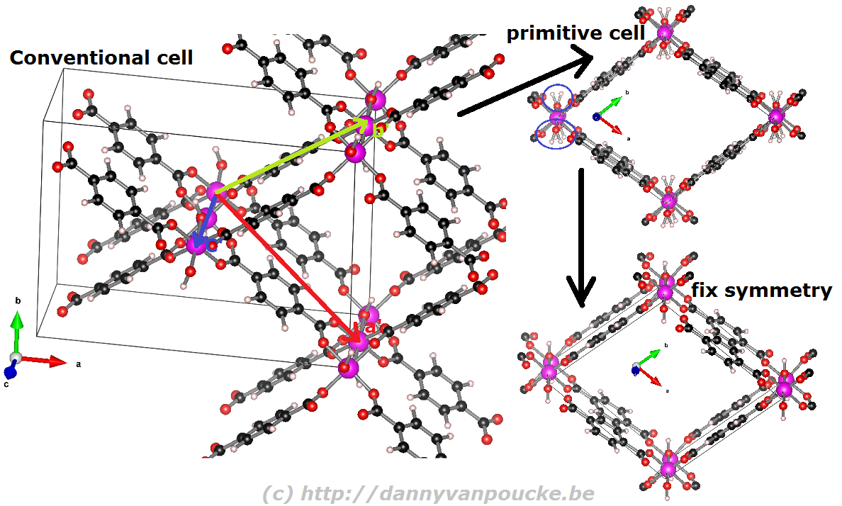
Comparison of a volume scan and an EOS-fit to fixed volume optimizations for a Metal-Organic Framework with MIL53/47 topology.

We just saw that for simple systems, the simple volume scan can already be too simple. For more complex systems like MOFs, similar problems can be seen. The simple volume scan, as for graphite gives a too sharp potential (with a very large bulk modulus). In addition, internal reordering of the atoms gives rise to very large changes in the energy, and the equilibrium volume can move quite a lot. It even depends on the spin-configuration.

In conclusion: the safest way to get a good equilibrium volume is unfortunately also the most expensive way. By means of an equation of state fit to a set of fixed volume structure optimizations the ground state (experimental) equilibrium volume can be found. As a bonus, the bulk modulus is obtained as well.

VASP-tutor: Convergence testing…step 0 in any computational project.

One of the main differences between theory and computational research is the fact that the latter has to deal with finite resources; mainly time and storage. Where theoretical calculations involve integrations over continuous spaces, infinite sums and basis sets, computational work performs numerical integrations as weighted sums over finite grids and cuts of infinite series. As an infinite number of operations would take an infinite amount of time, it is clear why numerical evaluations are truncated. If the contributions of an infinite series become smaller and smaller, it is also clear that at some point the contributions will become smaller than the numerical accuracy, so continuation beyond that point is …pointless.

In case of ab initio quantum mechanical calculations, we aim to get as accurate results at an as low computational cost as possible. Even with the current availability of computational resources, an infinite sum would still take an infinite amount of time. In addition, although parallelization can help out a lot in getting access to additional computational resources during the same amount of real time, codes are not infinitely parallel, so at some point adding more CPU’s will no longer speed up the calculations. Two important parameters in quantum mechanical calculations to play with are the basis set size (Or kinetic energy cut off, in case of plane wave basis sets. In which case this can also be related to the real space integration grid) and the integration grid for the reciprocal space (the k-point grid).

These two parameters are not unique to VASP, they are present in all quantum mechanical codes, but we will use VASP as an example here. The example system we will use is the α-phase of Cerium, using the PBE functional. The default cut-off energy used by VASP is 299 eV.

1.     Basis set size/Kinetic energy cut-off

What a basis set is and how it is defined depends strongly on the code. As such you are referred to the manual/tutorials of your code of interest.(VASP workshop) One important thing to remember, however, is the fact that although a plane wave basis set is “nicely behaved” (bigger basis = more accurate result) this is not true for all types of basis sets (Gaussian basis sets are an important example here).

How do you perform a convergence test?

  1. Get a geometry of your system of interest.

    This does not need to be a fully optimized geometry, an experimental geometry or a reasonable manually constructed geometry will do fine, as long as it gives you a converged result at the end of your static calculation. A convergence test should not depend on the exact geometry of your system. Rather it should tell you how well your setting converges your result with regard to the energy found on the potential energy surface.

  2. Fix all other settings

    (to reasonable values, although the settings should—to make your life somewhat sane—be independent with regard to convergence testing).
    VASP specific parameters of importance:

    • PREC : should be at least normal, but high or accurate are also possible
    • EDIFF : a value of 1.0E-6 to 1.0E-8 are reasonable for small systems. Note that this value should be much smaller than the accuracy you wish to obtain.
    • NSW = 0; IBRION = -1 : It should be static calculations.
    • ISPIN : If you intend to perform spin polarized calculations, you should also include this in your convergence tests. Yes it increases the computational cost, but remember that convergence tests will only take a fraction of the computational costs of your project, and can save you a lot of work and resources later on.
    • NBANDS : You may want to manually fix the number of electronic bands, which will allow for comparison of timing results.
    • LCHARG = .TRUE. ; ICHARG = 1: If you are not that interested in timing (or use average time of electronic loops instead of total CPU time), and want to speed things up a bit, you can use the electron density from a cheaper calculation as a starting point.
    • KPOINTS-file: use a non-trivial k-point set. e. unless you are looking at a molecule or very large system do not use the Gamma-point only.
  1. Loop over a set of kinetic energy cut-off values.

    These should be a simple static calculation. Make sure that each of the calculations finishes successfully, otherwise you will not be able to compare results and check convergence.

  2. Collect relevant data and check the convergence behavior.
ENCUT convergence

Convergence of the kinetic energy cut-off for alpha Ce using the PBE functional and a 9x9x9 k-point grid.

In our example, we used a 9x9x9 k-point set. Looking at the example, we first of all see how smoothly the total energy varies with regard to the ENCUT parameter. In addition, it is important to note that VASP has a correction term (search for EATOM in the OUTCAR file) implemented which greatly improves the energy convergence (compare the black and red curves). Unfortunately, it also leads to non-variational convergence (i.e. the energy does not become strictly smaller with increasing cut-off) which may lead to some confusion. However, the correction term performs really well, and allows you to use a kinetic energy cut-off which is much lower than what you would need to use without. In this case, the default cut-off misses the reference energy by about 10 meV. Without the correction, a cut-off of about 540 eV (almost double) is needed. From ENCUT=300 to 800 eV, you observe a plateau, so using a higher cut-off will not improve the energy much. However, other properties, such as the calculated forces or the hessian may improve in this region. For these parameters a higher cut-off may be beneficial, and their convergence as function of ENCUT should be checked if important for your work.

2.     K-point set

Similar as for the kinetic energy cut-off, if you are working with a periodic system you should check the convergence of your k-point set. However, if you are working with molecules/clusters your Brillouin zone reduces to a single point, so your k-point set should only consist of the Gamma point and no convergence testing is needed. More importantly, if you use a larger k-point set for such systems (molecules/clusters) you introduce artificial interaction between the periodic copies which should be avoided at all cost.

For bulk materials a k-point convergence check has a similar setup as the basis set convergence check. The main difference being the fact that for these calculation the basis set is kept constant (VASP: ENCUT = default cut-off, manually set) and the k-point set is varied. As such, if you are new to quantum mechanical calculations, or start using a new code, you can combine the two convergence checks and study the convergence behavior on a 2D surface.

KPOINTS convergence

K-point convergence of alpha-Cerium using the PBE functional and ENCUT=500 eV.

In our example, ENCUT was set to 500 eV. It is clear that an extended k-point set is important for small systems, as the Gamma-point only energy can be off by several eV. This is even the case for some large systems like MOFs. An important thing to remember with regard to k-point convergence, is the fact that this convergence is not strictly declining, it may show significant oscillations overshooting and undershooting the converged value. A convergence of 1 meV or less for the entire system is a goal to aim for. An exception may be the most large systems, but even then one should keep in mind the size of the energy barriers in that system. Using flexible MOFs as an example which show a large-pore to narrow-pore transition barrier of 10-20 meV per formula unit, k-point convergence should be much below this. Otherwise your system may accidentally cross this barrier during relaxation.

The blue curve shows the number of k-points in the irreducible Brillouin zone. For standard density functional theory calculations (LDA and GGA, not hybrid functionals) this is a measure of the computational cost, as the k-points can be calculated fully independently in parallel (and yes the blue scale is a log-scale as well). Because the first orders of magnitude in accuracy are quickly crossed ( from Gamma to 6x6x6 the energy error goes from the order of eV to meV) while the number of k-points doesn’t grow that quickly (from 1 to 28). As a result, one often performs structure optimizations in a stepped fashion, starting with a coarse grid steadily increasing the grid (unless pathological behavior is expected… MOFs again…yes, they do leave you with nightmares in this regard).

3.     Conclusions

Convergence testing is necessary, in theory, for each and every new system you look into. Luckily, VASP behaves rather nicely, such that over time you will know what to expect and your convergence tests will reduce in size significantly and become more focused. In the examples above we used the total energy as a reference, but this is not always the most important aspect to consider. In some cases you should check the convergence as function of the accuracy of the forces. In that case you generally will end up with more stringent criteria as energy converges rather nicely and quickly.

May your convergence curves be smooth and quick.

VASP-tutor: Creating a primitive unit cell from a conventional unit cell…for a MOF.

Ball-and-stick representation of diamond.

Ball-and-stick representation of diamond in two different unit cells. Left: primitive unit cell containing two atoms. All atoms at the vertices are periodic copies of the same one. Right: Conventional cubic unit cell containing eight atoms. Atoms at opposing faces are periodic copies, while all atoms at the vertices are periodic copies of the same atom.

When performing electronic structure calculations on complex systems, you prefer to do this on systems with as few atoms as possible. Such periodic cells are called unit cells. There are, however, two types of unit cells: Primitive unit cells and conventional unit cells.

A primitive unit cell is the smallest possible periodic cell of a crystalline material, making it extremely suited for calculations. Unfortunately, it is not always the nicest unit cell to work with, as it may be difficult to recognize it’s symmetry (cf. the example of diamond on the right). The conventional unit cell on the other hand shows the symmetry more clearly, but is not (always) the smallest possible unit cell. To make matters complicated and confusing, people often refer to both types as simply “unit cell”, which is not wrong, but the term unit cell is for many uniquely associated with only one of the two types.

When you are performing calculations on diamond, the conventional cell isn’t that large that standard calculations become impossible, even on a personal laptop or desktop. On the other hand, when you are studying a Metal-Organic Framework like the UiO-66(Zr) which contains 456 atoms in its conventional unit cell, you will be very happy to use the primitive unit cell with ‘merely’ 114 atoms. Also the MIL-47/53 topology which generally is studied using a conventional unit cell containing 72/76 can be reduced to a smaller primitive unit cell of only 36/38 atoms. Just as for the diamond primitive unit cell, this MIL47/53 primitive unit cell is not a nice cubic cell. Instead you end up with a lattice having lattice angles of seventy-something degrees.

Reduction of the MIL-53 conventional cell to the primitive cell

Reduction of the MIL-53 conventional cell to the primitive cell. The conventional cell is shown, extending slightly into the periodic copies. The primitive lattice vectors are shown as colored arrows. The folded primitive cell shows there was some symmetry-breaking in the hydroxy groups of the metal-oxide chain. Introducing some additional symmetry fixes this in the final primitive cell.

How to reduce a conventional unit cell to a primitive unit cell?

Before you start, and if you are using VASP, make sure you have the POSCAR file giving the atomic positions as Cartesian coordinates. (Using the HIVE-4 toolbox: Option TF, suboption 2 (Dir->Cart).)

If you do not use VASP, you can still make use of the scheme below.

  1. Open your structure using VESTA, and save it as “VASP” file: POSCAR.vasp (FileExport Datachoose “VASP” as filetype, select Cartesian Coordinates (don’t select the Convert to Niggli reduced cell as this only works for perfect crystal symmetry)).
  2. Open the file you just saved in a text editor (e.g. notepad or notepad++). The file format is quite straight forward.  The first line is a comment line while the second is a general scale-factor, which for our current purpose can be ignored. What is important to know is that the 3rd, 4th and 5th lines give the lattice vectors (a, b, and c). The 6th and 7th line give the order, type and number of atoms for each atomic species (In VASP 5.x, the older VASP 4.x format does not have a 6th line). The 8th line should say “Cartesian”. From the 9th line onward you get the atomic coordinates.
  3. Choose 1 atom in your conventional cell which you are going to use as reference point.
  4. Get the primitive unit cell lattice vectors by generating vectors from the reference atom. (cf. figure above) Using VESTA this can be done as follows:
    1. Open your conventional cell in VESTA (if you closed it after step 1).
    2. Use the distance selector (5th symbol from the top in the left-hand-side menu) and for each of the primitive lattice vectors, select the reference atom and it’s primitive copy.
      VESTA: Select distance VESTA: Fractional Coordinates
    3. Subtract the “fractional coordinates” of the selected atoms provided by VESTA to get a “fractional” primitive vector (the primitive a vector will be called aprim,frac )
    4. Multiply each of the conventional lattice vectors(aconv, bconv, and cconv) with the corresponding component of the fractional primitive vector, and add the resulting vectors to obtain the new primitive vector:

      ⇒  aprim = axprim,frac aconv + ayprim,frac bconv + azprim,frac cconv

      So imagine that the lattice vectors of the MOF above are  a = ( 20, 0, 0),  b = ( 0, 15, 0), and c = ( 0, 0, 5). And the primitive fractional a vector is found to be aprim,frac = ( 0.5, -0.5, 0.5). In this case the aprim vector will become: aprim = ( 10, 0, 0 ) + ( 0, -7.5, 0 ) + ( 0, 0, 2.5) = (10, -7.5, 2.5).

  5. Replace the conventional lattice vectors in the POSCAR.vasp file (cf. step 2) with the new primitive lattice vectors. Save the file.
  6. Open the POSCAR.vasp in VESTA. If everything went well, and the conventional cell wasn’t the real primitive cell already, you should see a nice new primitive cell with the equivalent atoms perfectly overlapping one-another. This is also the reason to have your starting geometry in Cartesian coordinates. If you would have your atomic positions as fractional coordinates this first check will not work at all. Furthermore, you would need to calculate the new fractional coordinates of the atoms in the primitive unit cell. If all is well, you can close POSCAR.VASP in VESTA. (If something is wrong: either you did something wrong, and you should start again, or it wasn’t actually a super cell of a primitive cell you started to construct.)
  7. Get the atoms of the primitive unit cell.
    1. Because our atomic positions are in Cartesian coordinates in our initial geometry file, we now just need to make a list of single copies of equivalent atoms. Using VESTA (the original structure file you still have open from step 1) you can click on each atom you wish to keep and write down their index (this is the first number you find on the line with Cartesian coordinates) … For example: In case of the MIL53-MOF you can select all metal and oxygen atoms of 1 chain, and two linker molecules.
    2. Remove all superfluous atoms (i.e. those of which you didn’t write down the index) from the POSCAR.vasp (using your text-editor). You may want to make a backup of this file before you start :-).
    3. Update the number of atoms on the 7th line of the POSCAR.vasp file, and check that the number is correct. The conventional cell should have had an integer multiple of the number of atoms in the primitive cell. Save the final structure as POSCAR_final.vasp .
    4. The POSCAR_final.vasp should contain both the new lattice vectors and a list of atoms for a single primitive unit cell. Check this by opening the file using VESTA, and make sure you didn’t remove too many or too few atoms. If not, go back to step (a) and double check. (If you are using the HIVE4-toolbox you can first transform POSCAR_final.vasp back to direct coordinates as this may make atoms visible which nicely overlap in Cartesian coordinates: Option TF, suboption 1 (Cart->Dir)  )
  8. Congratulations you have constructed a primitive cell from a conventional cell.

 As you can see, the method is quite simple and straight forward, albeit a bit tedious if you need to do this many times.

Enjoy your primitive unit cell!


PS: Small remark for those new to VESTA. You can use delete atoms in VESTA and store your structure again. This is useful if you want to play with a molecule. Unfortunately for a solid you need also to get new lattice vectors, which did not happen. As a result you end up with some atoms floating around in a periodically repeated box with the original lattice parameters. Steps 1-5 given above provide a simple way of not ending up in this situation, but require some typing on your part.

PS 2: The opposite transformation, from a primitive unit cell to a conventional unit cell, using VESTA, is shown in this youtube video.