December 2016 archive

Scaling of VASP 5.4.1 on TIER-1b BrENIAC

When running programs on HPC infrastructure, one of the first questions to ask yourself is: “How well does this program scale?

In applications for HPC resources, this question plays a central role, often with the additional remark: “But for your specific system!“. For some software packages this is an important remark, for other packages this remark has little relevance, as the package performs similarly for all input (or for given classes of input). The VASP package is one of the latter. For my current resource application at the Flemish TIER-1 I set out to do a more extensive scaling test of the VASP package. This is for 2 reasons. The first being the fact that I will be using a newer version of VASP: vasp 5.4.1 (I am currently using my own multiply patched version 5.3.3.). The second being the fact that I will be using a brand new TIER-1 machine (second Flemish TIER-1, as our beloved muk retired the end of 2016).

Why should I put in the effort to get access to resources on such a TIER-1 supercomputer? Because such machines are the life blood of the computational materials scientist. They are their sidekick in the quest for understanding of materials. Over the past 4 years, I was granted (and used) 20900 node-days of calculation time (i.e. over 8 Million hours of CPU time, or 916 years of calculation time) on the first TIER-1 machine.

Now back to the topic. How well does VASP 5.4.1 behave? That depends on the system at hand, and how good you choose the parallelization settings.

1. Parallelization in VASP

VASP provides several parameters which allow for straightforward parallelization of the simulation:

  • NPAR : This parameter can be set to parallelize over the electronic bands. As a consequence, the number of bands included in a calculation by VASP will be a multiple of NPAR. (Note : Hybrid calculations are an exception as they require NPAR to be set to the number of cores used per k-point.)
  • NCORE : The NCORE parameter is related to NPAR via NCORE=#cores/NPAR, so only one of these can be set.
  • KPAR : This parameter can be set to parallelize over the set of irreducible k-points used to integrate over the first Brillouin zone. KPAR should therefore best be a divisor of the number of irreducible k-points.
  • LPLANE : This boolean parameter allows one to switch on parallelization over plane waves. In general this will give rise to a small but consistent speedup (observed in previous scaling tests). As such we have chosen to set this parameter = .TRUE. for all calculations.
  • NSIM : Sets up a blocked mode for the RMM-DIIS algorithm. (cf. manual, and further tests by Peter Larsson). As our tests do not involve the RMM-DIIS algorithm, this parameter was not set.

In addition, one needs to keep the architecture of the HPC-system in mind as well: NPAR, KPAR and their product should be divisors of the number of nodes (and cores) used.

2. Results

Both NPAR and KPAR parameters can be set simultaneously and will have a serious influence on the speed of your calculations. However, not all possible combinations give the same speedup. Even worse, not all combinations are beneficial with regard to speed. This is best seen for a small 2 atom diamond primitive cell.
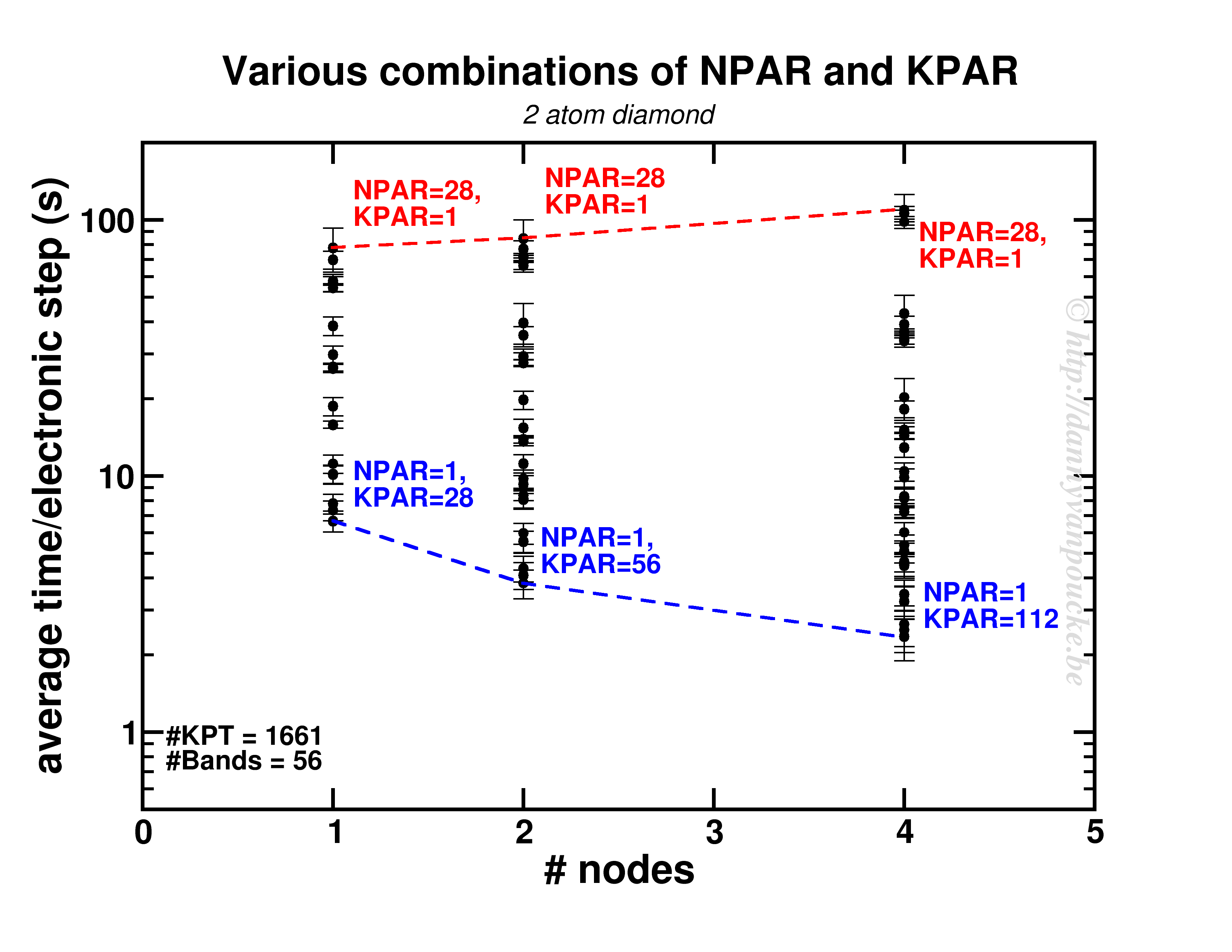
Timing primitive uni cell diamond.

Timing results for various combinations of the NPAR and KPAR parameters for a 2 atom primitive unit cell of diamond.

Two things are clear. First of all, switching on a parallelization parameter does not necessarily mean the calculation will speed up. In some case it may actually slow you down. Secondly, the best and worst performance is consistently obtained using the same settings. Best: KPAR = maximal, and NPAR = 1, worst: KPAR = 1 and NPAR = maximal.

This small system shows us what you can expect for systems with a lot of k-points and very few electronic bands ( actually, any real calculation on this system would only require 8 electronic bands, not 56 as was used here to be able to asses the performance of the NPAR parameter.)

In a medium sized system (20-100 atoms), the situation will be different. There, the number of k-points will be small (5-50) while the natural number of electronic bands will be large (>100). As a test-case I looked at my favorite Metal-Organic Framework: MIL-47(V).
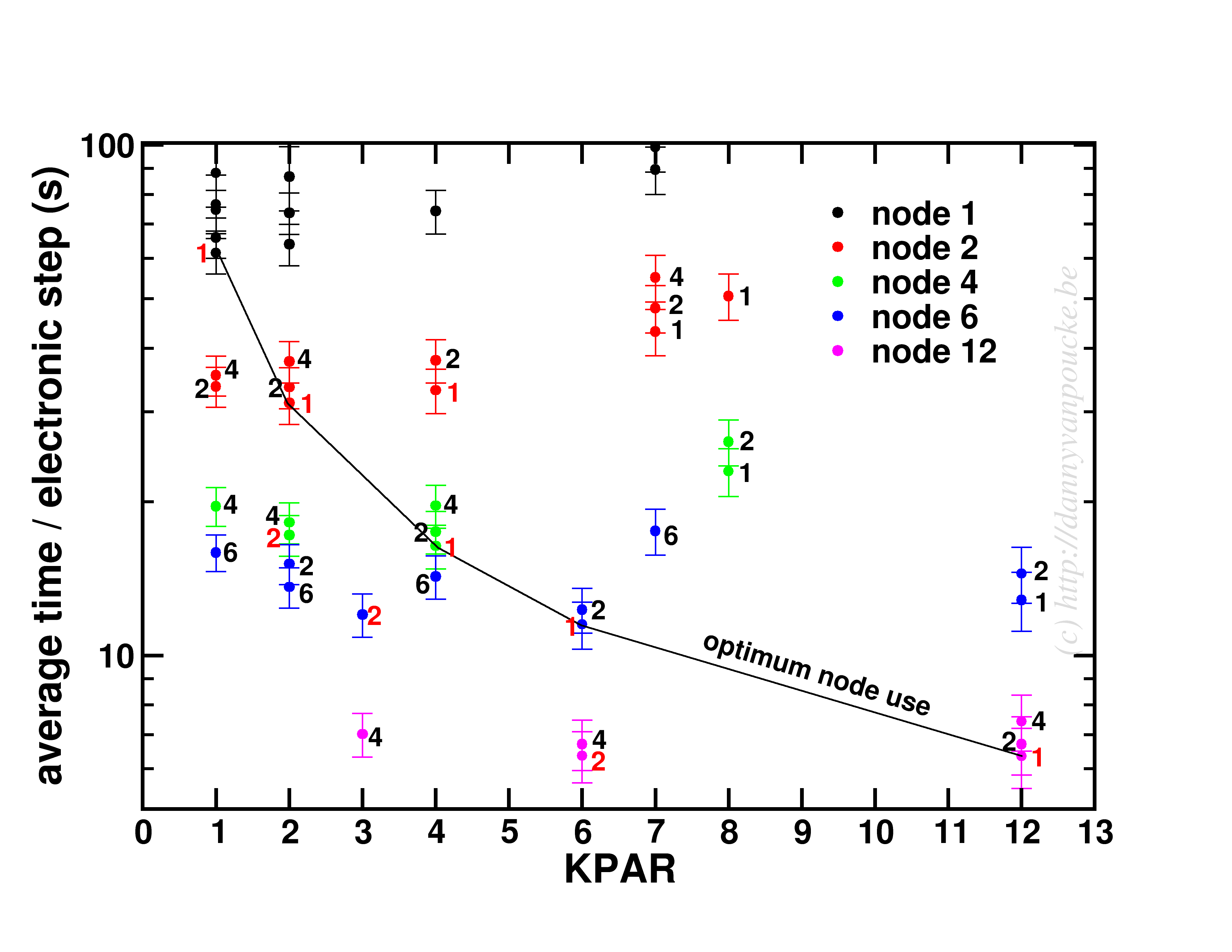
scaling of MIL-47(V) at PBE level

Timing results for several NPAR/KPAR combinations for the MIL-47(V) system.

This system has only 12 k-points to parallelize over, and 224 electronic bands. The spread per number of nodes is more limited than for the small system. In contrast, the general trend remains the same: KPAR=high, NPAR=low, with an optimum performance when KPAR=#nodes. Going beyond standard DFT, using hybrid functionals, also retains the same picture, although in some cases about 10% performance can be gained when using one half node per k-point. Unfortunatly, as we have very few k-points to start from, this will only be an advantage if the limiting factor is the number of nodes available.

An interesting behaviour is seen when one keeps the k-points/#nodes ratio constant:
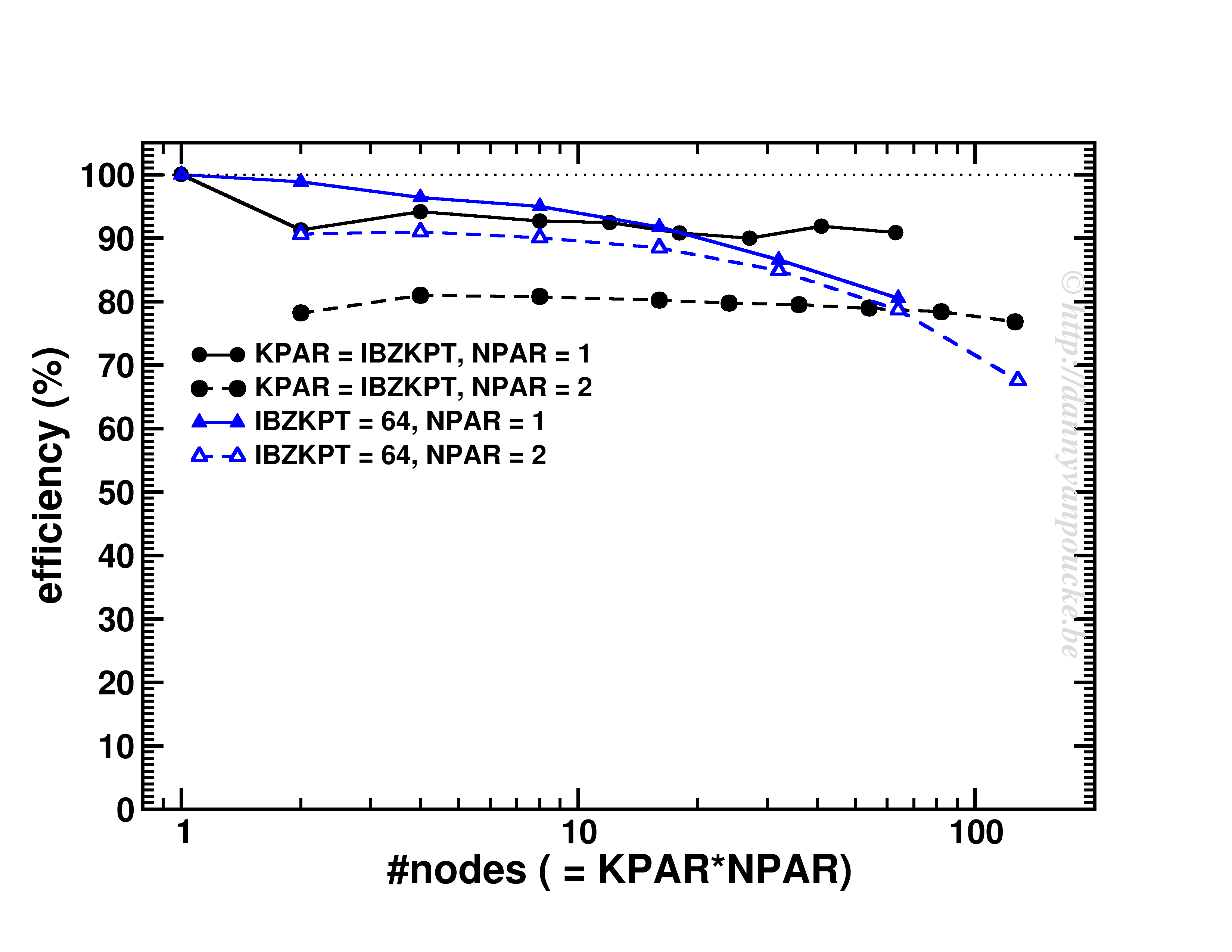
scaling at constant k-point/node ratio

Scaling behavior for either a constant number of k-points (for dense k-point grid in medium sized system) or constant k-point/#nodes ratio.

As you can see, VASP performs really well up to KPAR=#k-points (>80% efficiency). More interestingly, if the k-point/#node ratio is kept constant, the efficiency (now calculated as T1/(T2*NPAR) with T1 timing for a single node, and T2 for multiple nodes) is roughly constant. I.e. if you know the walltime for a 2-k-point/2-nodes job, you can use/expect the same for the same system but now considering 20-k-points/20-nodes (think Density of States and Band-structure calculations, or just change of #k-points due to symmetry reduction or change in k-point grid.)  😆

3. Conclusions and Guidelines

If one thing is clear from the current set of tests, it is the fact that good scaling is possible. How it is attained, however, depends greatly on the system at hand. More importantly, making a poor choice of parallelization settings can be very detrimental to the obtained speed-up and efficiency. Unfortunately when performing calculations on an HPC system, one has externally imposed limitations to work with:

  • Memory available per core
  • Number of cores per node[1]
  • Size of your system: #atoms, #k-points, & #bands

Here are some guidelines (some open doors as well):

  • Wherever possible k-point parallelization should be driven to a maximum (KPAR as large as possible). The limiting factor here is the actual number of k-points and the amount of memory available. The latter due to the fact that a higher value of KPAR leads to a higher memory requirement.[2]
  • Use the Γ-version of VASP for Γ-point only calculations. It reduces memory usage significantly (3.7Gb→ 2.8Gb/core for a 512 atom diamond system) and increases the computational efficiency, sometimes even by a factor of 2.
  • NPAR parallelization can be used to reduce the memory load for high KPAR calculations, but increasing KPAR will always outperform the same increase of NPAR.
  • In case only NPAR parallelization is available, due to too few k-points, and working with large systems, NPAR parallelization is your last resort, and will perform reasonably well, up to a point.
  • Electronic steps show very consistent timing, so scaling tests can be performed with only a 5-10 electronic steps, with standard deviations comparable in absolute size for PBE and HSE06.


In short:

K-point parallelism will save you, wherever possible !


[1] 28 is a lousy number in that regard as its prime-decomposition is 2x2x7, leaving little overlap with prime-decompositions of the number of k-points, which more often than you wish end up being prime numbers themselves 😥
[2] The small system’s memory requirements varied from 0.15 to 1.09 Gb/core for the different combinations.

Permanent link to this article: https://dannyvanpoucke.be/scaling-vasp-breniac-en/

Bachelor projects @ UHasselt/IMO

Black arts of computational materials science.

Today the projects for the third year bachelor students in physics were presented at UHasselt. I also contributed two projects, giving the students the opportunity to choose for a computational materials science project. During these projects, I hope to introduce them into the modern (black) arts of High-Performance Computing and materials modelling beyond empirical models.

The two projects focus each on a different aspect of what it is to be a computational materials scientist. One project focuses on performing quantum mechanical calculations using the VASP program, and analyzing the obtained results with existing software. This student will investigate the NV-defect complex in diamond in all its facets. The other project focuses on the development of new tools to investigate the data generated by simulation software like VASP. This student will extend the existing phonon module in the HIVE-toolbox and use it to analyse a whole range of materials, varying from my favourite Metal-Organic Framework to a girl’s best friend: diamond.

Calculemus solidi


A description of the projects in Dutch can be found here.

Permanent link to this article: https://dannyvanpoucke.be/baproj2017-en/

VASP-tutor: Convergence testing…step 0 in any computational project.

One of the main differences between theory and computational research is the fact that the latter has to deal with finite resources; mainly time and storage. Where theoretical calculations involve integrations over continuous spaces, infinite sums and basis sets, computational work performs numerical integrations as weighted sums over finite grids and cuts of infinite series. As an infinite number of operations would take an infinite amount of time, it is clear why numerical evaluations are truncated. If the contributions of an infinite series become smaller and smaller, it is also clear that at some point the contributions will become smaller than the numerical accuracy, so continuation beyond that point is …pointless.

In case of ab initio quantum mechanical calculations, we aim to get as accurate results at an as low computational cost as possible. Even with the current availability of computational resources, an infinite sum would still take an infinite amount of time. In addition, although parallelization can help out a lot in getting access to additional computational resources during the same amount of real time, codes are not infinitely parallel, so at some point adding more CPU’s will no longer speed up the calculations. Two important parameters in quantum mechanical calculations to play with are the basis set size (Or kinetic energy cut off, in case of plane wave basis sets. In which case this can also be related to the real space integration grid) and the integration grid for the reciprocal space (the k-point grid).

These two parameters are not unique to VASP, they are present in all quantum mechanical codes, but we will use VASP as an example here. The example system we will use is the α-phase of Cerium, using the PBE functional. The default cut-off energy used by VASP is 299 eV.

1.     Basis set size/Kinetic energy cut-off

What a basis set is and how it is defined depends strongly on the code. As such you are referred to the manual/tutorials of your code of interest.(VASP workshop) One important thing to remember, however, is the fact that although a plane wave basis set is “nicely behaved” (bigger basis = more accurate result) this is not true for all types of basis sets (Gaussian basis sets are an important example here).

How do you perform a convergence test?

  1. Get a geometry of your system of interest.

    This does not need to be a fully optimized geometry, an experimental geometry or a reasonable manually constructed geometry will do fine, as long as it gives you a converged result at the end of your static calculation. A convergence test should not depend on the exact geometry of your system. Rather it should tell you how well your setting converges your result with regard to the energy found on the potential energy surface.

  2. Fix all other settings

    (to reasonable values, although the settings should—to make your life somewhat sane—be independent with regard to convergence testing).
    VASP specific parameters of importance:

    • PREC : should be at least normal, but high or accurate are also possible
    • EDIFF : a value of 1.0E-6 to 1.0E-8 are reasonable for small systems. Note that this value should be much smaller than the accuracy you wish to obtain.
    • NSW = 0; IBRION = -1 : It should be static calculations.
    • ISPIN : If you intend to perform spin polarized calculations, you should also include this in your convergence tests. Yes it increases the computational cost, but remember that convergence tests will only take a fraction of the computational costs of your project, and can save you a lot of work and resources later on.
    • NBANDS : You may want to manually fix the number of electronic bands, which will allow for comparison of timing results.
    • LCHARG = .TRUE. ; ICHARG = 1: If you are not that interested in timing (or use average time of electronic loops instead of total CPU time), and want to speed things up a bit, you can use the electron density from a cheaper calculation as a starting point.
    • KPOINTS-file: use a non-trivial k-point set. e. unless you are looking at a molecule or very large system do not use the Gamma-point only.
  1. Loop over a set of kinetic energy cut-off values.

    These should be a simple static calculation. Make sure that each of the calculations finishes successfully, otherwise you will not be able to compare results and check convergence.

  2. Collect relevant data and check the convergence behavior.
ENCUT convergence

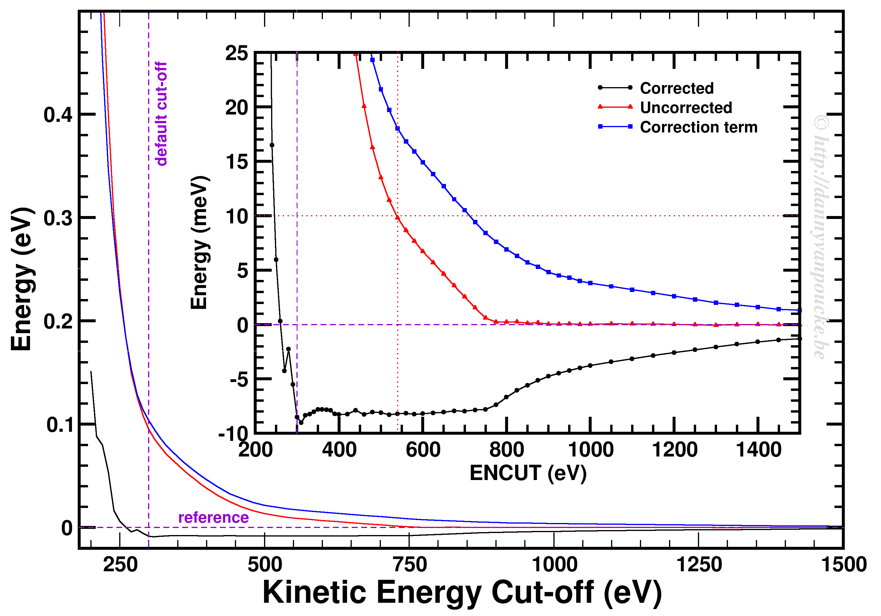
Convergence of the kinetic energy cut-off for alpha Ce using the PBE functional and a 9x9x9 k-point grid.

In our example, we used a 9x9x9 k-point set. Looking at the example, we first of all see how smoothly the total energy varies with regard to the ENCUT parameter. In addition, it is important to note that VASP has a correction term (search for EATOM in the OUTCAR file) implemented which greatly improves the energy convergence (compare the black and red curves). Unfortunately, it also leads to non-variational convergence (i.e. the energy does not become strictly smaller with increasing cut-off) which may lead to some confusion. However, the correction term performs really well, and allows you to use a kinetic energy cut-off which is much lower than what you would need to use without. In this case, the default cut-off misses the reference energy by about 10 meV. Without the correction, a cut-off of about 540 eV (almost double) is needed. From ENCUT=300 to 800 eV, you observe a plateau, so using a higher cut-off will not improve the energy much. However, other properties, such as the calculated forces or the hessian may improve in this region. For these parameters a higher cut-off may be beneficial, and their convergence as function of ENCUT should be checked if important for your work.

2.     K-point set

Similar as for the kinetic energy cut-off, if you are working with a periodic system you should check the convergence of your k-point set. However, if you are working with molecules/clusters your Brillouin zone reduces to a single point, so your k-point set should only consist of the Gamma point and no convergence testing is needed. More importantly, if you use a larger k-point set for such systems (molecules/clusters) you introduce artificial interaction between the periodic copies which should be avoided at all cost.

For bulk materials a k-point convergence check has a similar setup as the basis set convergence check. The main difference being the fact that for these calculation the basis set is kept constant (VASP: ENCUT = default cut-off, manually set) and the k-point set is varied. As such, if you are new to quantum mechanical calculations, or start using a new code, you can combine the two convergence checks and study the convergence behavior on a 2D surface.

KPOINTS convergence

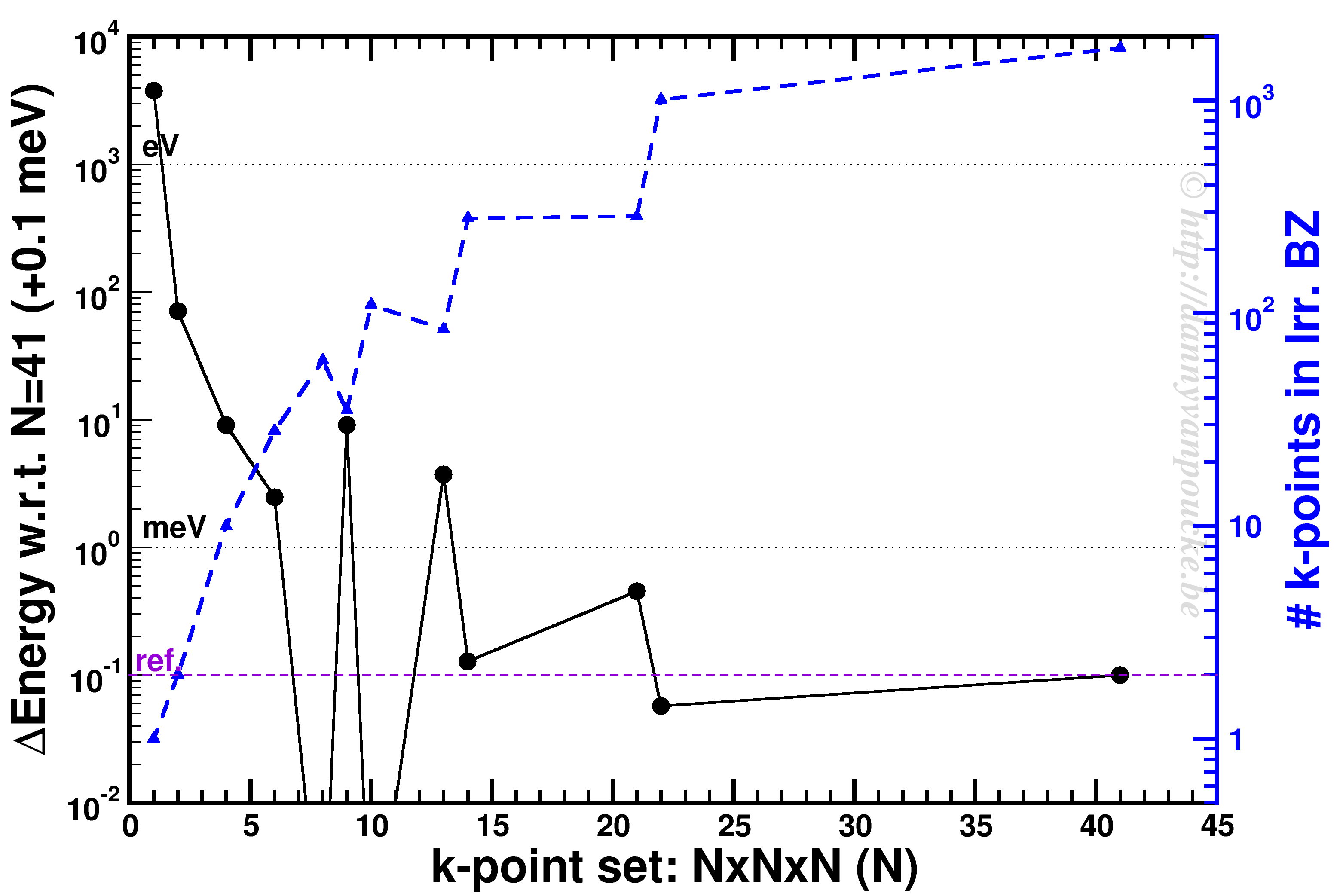
K-point convergence of alpha-Cerium using the PBE functional and ENCUT=500 eV.

In our example, ENCUT was set to 500 eV. It is clear that an extended k-point set is important for small systems, as the Gamma-point only energy can be off by several eV. This is even the case for some large systems like MOFs. An important thing to remember with regard to k-point convergence, is the fact that this convergence is not strictly declining, it may show significant oscillations overshooting and undershooting the converged value. A convergence of 1 meV or less for the entire system is a goal to aim for. An exception may be the most large systems, but even then one should keep in mind the size of the energy barriers in that system. Using flexible MOFs as an example which show a large-pore to narrow-pore transition barrier of 10-20 meV per formula unit, k-point convergence should be much below this. Otherwise your system may accidentally cross this barrier during relaxation.

The blue curve shows the number of k-points in the irreducible Brillouin zone. For standard density functional theory calculations (LDA and GGA, not hybrid functionals) this is a measure of the computational cost, as the k-points can be calculated fully independently in parallel (and yes the blue scale is a log-scale as well). Because the first orders of magnitude in accuracy are quickly crossed ( from Gamma to 6x6x6 the energy error goes from the order of eV to meV) while the number of k-points doesn’t grow that quickly (from 1 to 28). As a result, one often performs structure optimizations in a stepped fashion, starting with a coarse grid steadily increasing the grid (unless pathological behavior is expected… MOFs again…yes, they do leave you with nightmares in this regard).

3.     Conclusions

Convergence testing is necessary, in theory, for each and every new system you look into. Luckily, VASP behaves rather nicely, such that over time you will know what to expect and your convergence tests will reduce in size significantly and become more focused. In the examples above we used the total energy as a reference, but this is not always the most important aspect to consider. In some cases you should check the convergence as function of the accuracy of the forces. In that case you generally will end up with more stringent criteria as energy converges rather nicely and quickly.

May your convergence curves be smooth and quick.

Permanent link to this article: https://dannyvanpoucke.be/vasp-tutor-convergence-testing-en/

MRS seminar: Topological Insulators

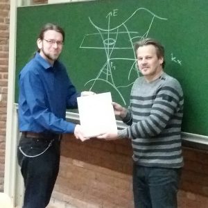
Bart Sorée receives a commemorative frame of the event. Foto courtesy of Rajesh Ramaneti.

Today I have the pleasure of chairing the last symposium of the year of the MRS chapter at UHasselt. During this invited lecture, Bart Sorée (Professor at UAntwerp and KULeuven, and alumnus of my own Alma Mater) will introduce us into the topic of topological insulators.

This topic became unexpectedly a hot topic as it is part of the 2016 Nobel Prize in Physics, awarded last Saturday.

This year’s Nobel prize in physics went to: David J. Thouless (1/2), F. Duncan M. Haldane (1/4) and J. Michael Kosterlitz (1/4) who received it

“for theoretical discoveries of topological phase transitions and topological phases of matter.”

On the Nobel Prize website you can find this document which gives some background on this work and explains what it is. Beware that the explanation is rather technical and at an abstract level. They start with introducing the concept of an order parameter. You may have heard of this in the context of dynamical systems (as I did) or in the context of phase transitions. In the latter context, order parameters are generally zero in one phase, and non-zero in the other. In overly simplified terms, one could say an order parameter is a kind of hidden variable (not to be mistaken for a hidden variable in QM) which becomes visible upon symmetry breaking. An example to explain this concept.

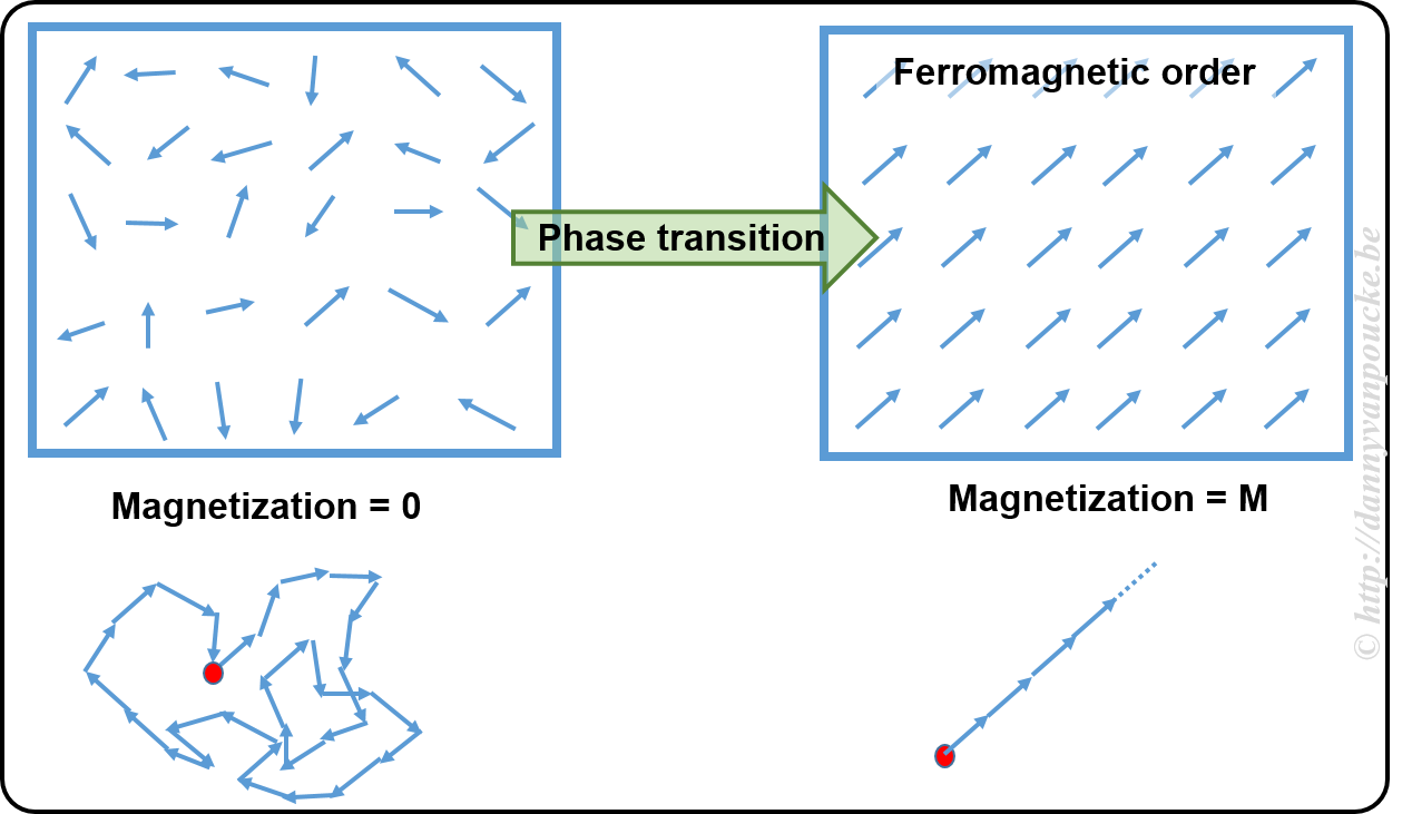
Example: Magnetization of a ferromagnet.

In a ferromagnetic material, the atoms have what is called a spin (imagine it as a small magnetic needle pointing in a specific direction, or a small arrow). At high temperature these spins point randomly in all possible directions, leading to a net zero magnetization (the sum of all the small arrows just lets you run in circles going nowhere). This magnetization is the order parameter. At the high temperature, as there is no preferred direction, the system is invariant under rotation and translations (i.e. if you shift it a bit or you rotate it, or both you will not see a difference) When the temperature is lower, you will cross what is called a critical temperature. Below this temperature all spins will start to align themselves parallel, giving rise to a non-zero magnetization (if all arrows point in the same direction, their sum is a long arrow in that direction). At this point, the system has lost the rotational invariance (because all spins point in  direction, you will know when someone rotated the system) and the symmetry is said to have broken.

Within the context of phase transitions, order parameters are often temperature dependent. In case of topological materials this is not the case. A topological material has a topological order, which means both phases are present at absolute zero (or the temperature you will never reach in any experiment no matter how hard you try) or maybe better without the presence of temperature (this is more the realm of computational materials science, calculations at 0 Kelvin actually mean without temperature as a parameter). So the order parameter in a topological material will not be temperature dependent.

Topological insulators

To complicate things, topological insulators are materials which have a topological order which is not as the one defined above 😯 —yup why would we make it easy 🙄 . It gets even worse, a topological insulator is conducting.

OK, before you run away or loose what is remaining of your sanity. A topological insulator is an insulating material which has surface states which are conducting. In this it is not that different from many other “normal” insulators. What makes it different, is that these surface states are, what is called, symmetry protected. What does this mean?

In a topological insulator with 2 conducting surface states, one will be linked to spin up and one will be linked to spin down (remember the ferromagnetism story of before, now the small arrows belong to the separate electrons and exist only in 2 types: pointing up=spin up, and pointing down=spin down). Each of these surface states will be populated with electrons. One state with electrons having spin up, the other with electrons having spin down. Next, you need to know that these states also have a real-space path let the electrons run around the edge of material. Imagine them as one-way streets for the electrons. Due to symmetry the two states are mirror images of one-another. As such, if electrons in the up-spin state more left, then the ones in the down-spin state move right. We are almost there, no worries there is a clue. Now, where in a normal insulator with surface states the electrons can scatter (bounce and make a U-turn) this is not possible in a topological insulator. But there are roads in two directions you say? Yes, but these are restricted. And up-spin electron cannot be in the down-spin lane and vice versa. As a result, a current going in such a surface state will show extremely little scattering, as it would need to change the spin of the electron as well as it’s spatial motion. This is why it is called symmetry protected.

If there are more states, things get more complicated. But for everyone’s sanity, we will leave it at this.  😎

Permanent link to this article: https://dannyvanpoucke.be/topological-insulators-en/