For many people around the world, last weekend was highlighted by a half-yearly recurring ritual: switching to/from daylight saving time. In Belgium, this goes hand-in-hand with another half-yearly ritual; The discussion about the possible benefits of abolishing of daylight saving time. Throughout the last century, daylight saving time has been introduced on several occasions. The most recent introduction in Belgium and the Netherlands was in 1977. At that time it was intended as a measure for conserving energy, due to the oil-crises of the 70’s. (In Belgium, this makes it painfully modern due to the current state of our energy supplies: the impending doom of energy shortages and the accompanying disconnection plans which will put entire regions without power in case of shortages.)
The basic idea behind daylight saving time is to align the daylight hours with our working hours. A vision quite different from that of for example ancient Rome, where the daily routine was adjusted to the time between sunrise and sunset. This period was by definition set to be 12 hours, making 1h in summer significantly longer than 1h in winter. As children of our time, with our modern vision on time, it is very hard to imagine living like this without being overwhelmed by images of of impending doom and absolute chaos. In this day and age, we want to know exactly, to the second, how much time we are spending on everything (which seems to be social media mostly 😉 ). But also for more important aspects of life, a more accurate picture of time is needed. Think for example of your GPS, which will put you of your mark by hundreds of meters if your uncertainty in time is a mere 0.000001 seconds. Also, police radar will not be able to measure the speed of your car with the same uncertainty on its timing.
Turing back to the Roman vision of time, have you ever wondered why “the day” is longer during summer than during winter? Or, if this difference is the same everywhere on earth? Or, if the variation in day length is the same during the entire year?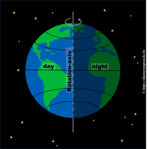
Our place on earth
To answer these questions, we need a good model of the world around us. And as is usual in science, the more accurate the model, the more detailed the answer.
Let us start very simple. We know the earth is spherical, and revolves around it’s axis in 24h. The side receiving sunlight we call day, while the shaded side is called night. If we assume the earth rotates at a constant speed, then any point on its surface will move around the earths rotational axis at a constant angular speed. This point will spend 50% of its time at the light side, and 50% at the dark side. Here we have also silently assumed, the rotational axis of the earth is “straight up” with regard to the sun.
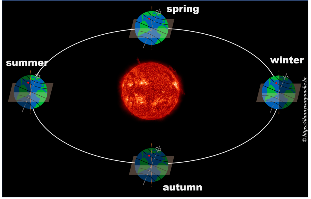
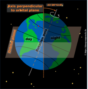 In reality, this is actually not the case. The earths rotational axis is tilted by about 23° from an axis perpendicular to the orbital plane. If we now consider a fixed point on the earths surface, we’ll note that such a point at the equator still spends 50% of its time in the light, and 50% of its time in the dark. In contrast, a point on the northern hemisphere will spend less than 50% of its time on the daylight side, while a point on the southern hemisphere spends more than 50% of its time on the daylight side. You also note that the latitude plays an important role. The more you go north, the smaller the daylight section of the latitude circle becomes, until it vanishes at the polar circle. On the other hand, on the southern hemisphere, if you move below the polar circle, the point spend all its time at the daylight side. So if the earths axis was fixed with regard to the sun, as shown in the picture, we would have a region on earth living an eternal night (north pole) or day (south pole). Luckily this is not the case. If we look at the evolution of the earths axis, we see that it is “fixed with regard to the fixed stars”, but makes a full circle during one orbit around the sun.* When the earth axis points away from the sun, it is winter on the northern hemisphere, while during summer it points towards the sun. In between, during the equinox, the earth axis points parallel to the sun, and day and night have exactly the same length: 12h.
So, now that we know the length of our daytime varies with the latitude and the time of the year, we can move one step further.
How does the length of a day vary, during the year?
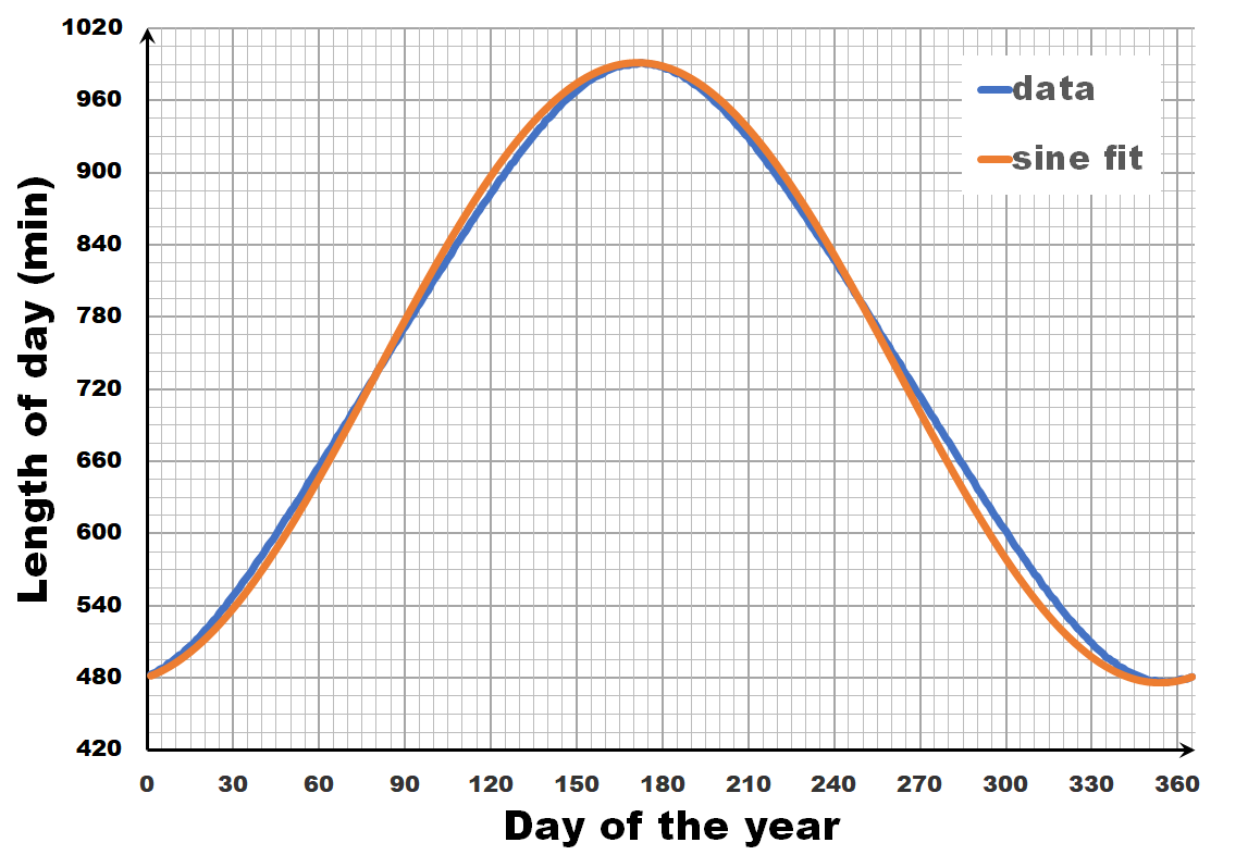
The length of the day varies over the year, with the longest and shortest days indicated by the summer and winter solstice. The periodic nature of this variation may give you the inclination to consider it as a sine wave, a sine-in-the-wild so to speak. Now let us compare a sine wave fitted to actual day-time data for Brussels. As you can see, the fit is performing quite well, but there is a clear discrepancy. So we can, and should do better than this.
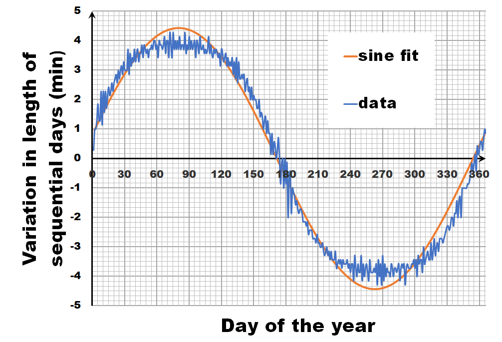
 Instead of looking at the length of each day, let us have a look at the difference in length between sequential days.** If we calculate this difference for the fitted sine wave, we again get a sine wave as we are taking a finite difference version of the derivative. In contrast, the actual data shows not a sine wave, but a broadened sine wave with flat maximum and minimum. You may think this is an error, or an artifact of our averaging, but in reality, this trend even depends on the latitude, becoming more extreme the closer you get to the poles.
 This additional information, provides us with the extra hint that in addition to the axial tilt of the earth axis, we also need to consider the latitude of our position. What we need to calculate is the fraction of our latitude circle (e.g. for Brussels this is 50.85°) that is illuminated by the sun, each day of the year. With some perseverance and our high school trigonometric equations, we can derive an analytic solution, which can then be calculated by, for example, excel.
 Some calculations
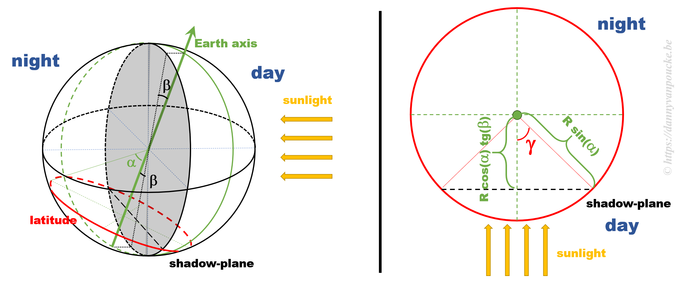
The figure above shows a 3D sketch of the situation on the left, and a 2D representation of the latitude circle on the right. α is related to the latitude, and β is the angle between the earth axis and the ‘shadow-plane’ (the plane between the day and night sides of earth). As such, β will be maximal during solstice (±23°26’12.6″) and exactly equal to zero at the equinox—when the earth axis lies entirely in the shadow-plane. This way, the length of the day is equal to the illuminated fraction of the latitude circle: 24h(360°-2γ). γ can be calculated as cos(γ)=adjacent side/hypotenuse in the right hand side part of the figure above. If we indicate the earth radius as R, then the hypotenuse is given by Rsin(α). The adjacent side, on the other hand, is found to be equal to R’sin(β), where R’=B/cos(β), and B is the perpendicular distance between the center of the earth and the plane of the latitude circle, or B=Rcos(α).
Combining all these results, we find that the number of daylight hours is:
24h*{360°-2arccos[cotg(α)tg(β)]}
How accurate is this model?
All our work is done, the actual calculation with numbers is a computer’s job, so we put excel to work. For Brussels we see that our model curve very nicely and smoothly follows the data (There is no fitting performed beyond setting the phase of the model curve to align with the data). We see that the broadening is perfectly shown, as well as the perfect estimate of the maximum and minimum variation in daytime (note that this is not a fitting parameter, in contrast to the fit with the sine wave). If you want to play with this model yourself, you can download the excel sheet here. While we are on it, I also drew some curves for different latitudes. Note that beyond the polar circles this model can not work, as we enter regions with periods of eternal day/night.

After all these calculations, be honest:
You are happy you only need to change the clock twice a year, don’t you. 🙂
* OK, in reality the earths axis isn’t really fixed, it shows a small periodic precession with a period of about 41000 years. For the sake of argument we will ignore this.
** Unfortunately, the data available for sunrises and sunsets has only an accuracy of 1 minute. By taking averages over a period of 7 years, we are able to reduce the noise from ±1 minute to a more reasonable value, allowing us to get a better picture of the general trend.
External links


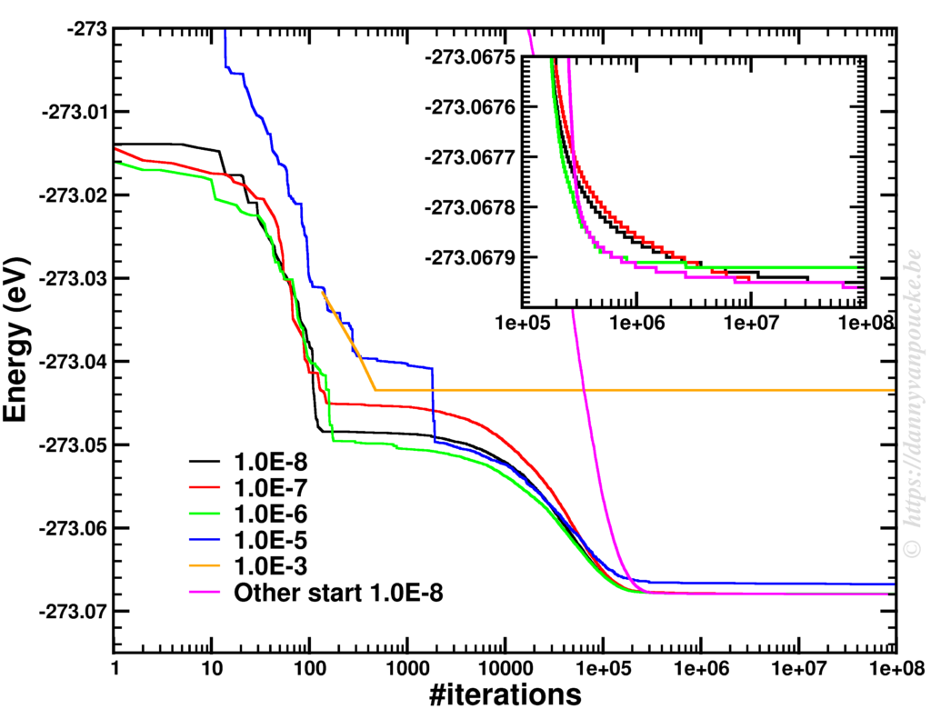
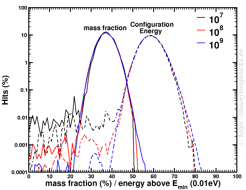
 Last few months, I finally was able to remove something which had been lingering on my to-do list for a very long time: studying debugging in Fortran. Although I have been programming in Fortran for over a decade, and getting quite good at it, especially in the more exotic aspects such as OO-programming, I never got around to learning how to use decent debugging tools. The fact that I am using Fortran was the main contributing factor. Unlike other languages, everything you want to do in Fortran beyond number-crunching in procedural code has very little documentation (e.g., easy dll’s for objects), is not natively supported (e.g., find a good IDE for fortran, which also supports modern aspects like OO, there are only very few who attempt), or you are just the first to try it (e.g., fortran programs for android :o, definitely on my to-do list). In a long bygone past I did some debugging in Delphi (for my STM program) as the debugger was nicely integrated in the IDE. However, for Fortran I started programming without an IDE and as such did my initial debugging with well placed write statements. And I am a bit ashamed to say, I’m still doing it this way, because it can be rather efficient for a large code spread over dozens of files with hundreds of procedures.
 Having fun with my xmgrace-fortran library and fractal code!

 In reality, this is actually not the case. The earths rotational axis is tilted by about 23° from an axis perpendicular to the orbital plane. If we now consider a fixed point on the earths surface, we’ll note that such a point at the equator still spends 50% of its time in the light, and 50% of its time in the dark. In contrast, a point on the northern hemisphere will spend less than 50% of its time on the daylight side, while a point on the southern hemisphere spends more than 50% of its time on the daylight side. You also note that the latitude plays an important role. The more you go north, the smaller the daylight section of the latitude circle becomes, until it vanishes at the polar circle. On the other hand, on the southern hemisphere, if you move below the polar circle, the point spend all its time at the daylight side. So if the earths axis was fixed with regard to the sun, as shown in the picture, we would have a region on earth living an eternal night (north pole) or day (south pole). Luckily this is not the case. If we look at the evolution of the earths axis, we see that it is “fixed with regard to the fixed stars”, but makes a full circle during one orbit around the sun.
 This summer, I had the pleasure of being interviewed by
 The power of models in physics, originates from keeping only the most important and relevant aspects. Such approximations provide a simplified picture and allow us to understand the driving forces behind nature itself. However, in this context,