Most commented posts
- Phonons: shake those atoms — 3 comments
- Start to Fortran — 1 comment


Nov 28 2015
Met dit essay nam ik deel aan de Robbert Dijkgraaf essay-prijs 2015.
Dit jaar was het thema verbeelding, en in mijn bijdrage doe ik een
poging de rol van verbeelding naar voren te brengen binnen
computationeel materiaalonderzoek. Ik probeer eveneens uit te
leggen hoe ik computationeel onderzoek zie als onderzoeksdomein.
Een vertaling naar het Engels kan hier gevonden worden.
Stel je een wereld voor waarin je atomen kunt zien. Meer nog, je kunt ze stapelen als legoblokken en manipuleren naar eigen goeddunken. Stel je een wereld voor waarin je de natuurwetten kunt aan- of afzetten, een wereld waar je zelf nieuwe natuurwetten kunt schrijven. In zo een wereld heb jij het voor het zeggen. Welkom in mijn wereld, de wereld van het “computationele materiaalonderzoek“.
Het zou een mooi begin zijn van een reclamespot voor dit onderzoeksgebied. In de bijhorende clip krijg je in elkaar overgaande beelden te zien van supercomputers enerzijds en animaties van chemische en biochemische processen op de atomaire schaal anderzijds. Het geheel wordt dan doorgelinkt aan onze eigen toekomst met sciencefictionachtige laboratoria waar de berekende materialen direct worden omgezet tot nieuwe medicijnen, flinterdunne beeldschermen en toepassing voor de ruimtevaart. De steeds sneller elkaar opvolgende beelden  culmineren dan in de slotslogan: “Simuleer de toekomst!” met als onderschrift de aansporing om computationeel materiaalonderzoek te gaan studeren. Ik stel me voor dat zo’n reclameclip wel tot de verbeelding zou spreken. Het spreekt onze menselijke drang om te creëren aan met de belofte dat je alles kunt, als je het je maar kunt voorstellen. Je verbeelding is de enige beperkende factor.
Zoals bij de meeste reclamespots wordt ook in deze de werkelijkheid iets mooier voorgesteld dan ze is. Zoals voor elke andere wetenschapper geldt immers dat je bijdrage aan de vooruitgang beperkter is dan je zou willen. De gepresenteerde goddelijke almacht en alwetendheid liggen wel binnen handbereik. Als computationeel onderzoeker heb je immers absolute controle over de plaatsing van atomen en de inwerkende krachten, iets waar een experimenteel onderzoeker deels is overgelaten aan de grillen van de natuur en zijn of haar apparatuur. Deze controlevrijheid laat je toe, binnen een computer, elke wereld te creëren die je maar kunt bedenken.
Als wetenschapper wil je de wereld om je heen begrijpen, wat bovenstaande vrijheden inperkt, tenzij je ervoor kiest om in een team van computergame-designers aan de slag gaan. Dit betekent niet dat je creativiteit wordt beknot, integendeel. Waar bij het ontwerpteam het volledige verhaal bekend is, inclusief de regels en natuurwetten van de wereld waarin je speelt, is dat niet het geval bij computationeel materiaalonderzoek. Meer nog, vaak is het net je opdracht het verhaal gaandeweg te ontdekken, inclusief de natuurwetten die relevant zijn. Je wordt als het ware een verteller die telkens nieuwe verhalen moet bedenken, of bestaande plots moet aanpassen, uitbreiden of beperken, tot de verhaallijn past in de vorm van de werkelijkheid.
Je staat er gelukkig niet alleen voor om een goede afloop te regelen. Je wordt bijgestaan door je trouwe sidekick: je supercomputer. Deze is in staat met brute kracht de gekste plotwendingen door te rekenen. Op basis van jouw inleidende hoofdstuk, waarin je de wereld en haar natuurwetten schetst, zal hij het verhaal verder laten ontplooien. Door dan de juiste vragen te stellen en de antwoorden met de werkelijkheid te vergelijken kom je erachter waar je verhaal nog niet helemaal in de werkelijkheid past.
Hoe je je inleidende hoofdstuk daarop moet aanpassen verschilt per geval. Soms is het duidelijk wat er aan de hand is: er ontbreekt een cruciaal personage (bijvoorbeeld een onzuiverheidsatoom dat het kristaalrooster verstoord) of het personage woont op de foute plaats (toch niet op de plaats van atoom A, atoom B dan maar?). Moeilijker wordt het als sommige personages weigeren de hun toebedeelde rol te spelen (Die platina-atomen zijn onzichtbaar voor de rastertunnelmicroscoop, wie speelt nu de rol van de zichtbare nanodraad?). De lastigste situatie is wanneer een volledige herschrijving van het inleidende hoofdstuk nodig is. Hierdoor krijg je te veel vrijheid in handen, terwijl het net de gekende beperkingen zijn die je houvast geven bij het opstellen van het verhaal. Je hebt dan een idee nodig dat je een link geeft met de werkelijkheid. Inspiratie kan hier velerlei vormen aannemen en op willekeurig moment komen. Een bekende anekdote is deze van de theoretische chemicus Kekulé, die in een dagdroom een slang zichzelf in de staart zag bijten en daardoor de ringvormige structuur van de benzeenmolecule uitdokterde. Zulke wonderlijk probleemoplossende gedachtenkronkels komen zelden spontaan, maar zijn veeleer het gevolg van lang en intens werk op eenzelfde vraagstuk. Dergelijke situaties drijven je tot het uiterste, je moet je immers iets voorstellen waar je nooit eerder aan gedacht hebt. In managementkringen wordt zoiets “buiten het kader denken” genoemd, wat bedrieglijk eenvoudig klinkt. Je mag immers niet vergeten dat voor onderzoek dit niet betekent dat alles plots toegelaten is (met andere woorden, je mag het kader zeker niet uit het oog verliezen bij het dagdromen).
Als computationeel materiaalonderzoeker moet je dus je almacht over je virtuele wereld combineren met je eigen vermogen nieuwe werelden in gedachten te scheppen, in de hoop zo onderweg een glimp van de buitenwereld in je siliciumchip op te vangen.
Nov 26 2015
In the current academic world, there are two often heard mantra’s: publish more and publish open access. In a world where there are ever more researchers competing for limited financial resources, distribution of these resources needs persistent justification. While funding agencies seem to be in a relentless quest for ‘excellence‘ in research (or just more publications, because that is easily quantifiable), a new side-quest has emerged: ‘open access publication’. This side-quest can either be considered as a move against scientific publishers requesting huge subscription fees from universities or as a further way of justifying what is being done with tax-payer money (with open access the tax-payer can go find out him-/herself ).
 The publish or perish culture has lead to the birth of predatory journals and publishers. These journals more and more act as regular journals (e.g. promising/claiming peer review). However, in the end, as long as a publishing fee is paid your paper will get published. Researchers of ill intend can easily get their work published in such journals and as such inflate their CV. Unfortunately, also poorly informed researchers, with no ill intend, can be trapped by such journals. These journals use rather aggressive mailing campaigns (I generally get a few of these e-mails every week on my academic mail account) and present journals with names rather similar to well established journals. Luckily, after a while you start to recognize the usual predatory publishers such as scirp, bentham science publishers or hindawi publishing. The setup of their mailings are rather similar. There are two main types: the professional journal type and the personal interest type. The first setup starts by presenting their journal as brand new and of high interest to field, indicating that the journal is indexed in several listings (giving it the impression of validity) and finally that there is a publishing charge (which generally isn’t that steep, 100-200$). The second type approaches you noting they have read one of your recent publications, and consider it to be of great quality and interest to the world. After sufficient flattery you are then invited to publish new work with them (which can be done at a special discount).
Lately, with the recent quest for open-access publishing (funding agencies/universities requiring of their researchers to publish open access*) these predatory journals moved on. Nowadays, you do not need to pay for publication any longer, you now pay for the “open access” of your work. In my case, the most recent invitation was by intechopen. I was invited to write a chapter in a book on Metal-Organic Frameworks, and since it is open access, it would only cost 670€ in processing charges. No thank you. After a reminder by the publishing process manager I put in the effort to check if they are already blacklisted as a predatory journal/publisher, and yes they are: Jeffrey Beal’s list of predatory publishers. (For the record, if you are invited to write a paper/book-chapter there should be no page/processing charges at all, on the contrary you should actually get a (small) fee.)
This question is becoming harder to answer every year. With open access, also regular publishers have discovered a new gold-mine which they are rather eager to excavate. Also with the huge flood of publications that all need to be reviewed by multiple referees, quality in that area starts to degrade slightly but steadily. So what to do?
*They, however, tend to have conflicting standards in this regard. You are on the one hand encouraged to publish in high impact journals and you are required to publish open access. On the other hand however, no additional funding is provided to pay for the open access costs in high impact journals. These costs are often several thousand euros for one publication, or more than half an FWO bench-fee which is to be used for visiting conferences, buying lab equipment or computational resources.
Nov 13 2015
| Authors: | Thomas Bogaerts, Louis Vanduyfhuys, Danny E.P. Vanpoucke, Jelle Wieme, Michel Waroquier, Pascal Van Der Voort, and Veronique Van Speybroeck, |
| Journal: | CrystEngComm. 17(45), 8565 (2015) |
| doi: | 10.1039/C5CE90198G |
| IF(2015): | 3.849 |
| export: | bibtex |
| pdf: | <CrystEngComm> |
The cover image depicts an X-ray beam hitting a sample of MIL-47(V) Metal-Organic Framework (reddish powder), resulting in an X-ray diffraction pattern. This leads to the atomic structure on the left, Where the spin-densities are indicated for the anti-ferromagnetic ground state. (The related paper can be found here.)

Nov 05 2015
| Authors: | Kevin Hendrickx, Danny E.P. Vanpoucke, Karen Leus, Kurt Lejaeghere, Andy Van Yperen-De Deyne, Veronique Van Speybroeck, Pascal Van Der Voort, and Karen Hemelsoet |
| Journal: | Inorg. Chem. 54(22), 10701-10710 (2015) |
| doi: | 10.1021/acs.inorgchem.5b01593 |
| IF(2015): | 4.820 |
| export: | bibtex |
| pdf: | <Inorg.Chem.> |
Linker-functionalization of UiO-66 modifies the optical band gap and thus the color of the MOF.
A combined theoretical and experimental study is performed in order to elucidate the eff ects of linker functional groups on the photoabsorption properties of UiO-66-type materials. This study, in which both mono- and di-functionalized linkers (with X= -OH, -NH2, -SH) are studied, aims to obtain a more complete picture on the choice of functionalization. Static Time-Dependent Density Functional Theory (TD-DFT) calculations combined with Molecular Dynamics simulations are performed on the linkers and compared to experimental UV/VIS spectra, in order to understand the electronic eff ects governing the absorption spectra. Di-substituted linkers show larger shifts compared to mono-substituted variants, making them promising candidates for further study as photocatalysts. Next, the interaction between the linker and the inorganic part of the framework is theoretically investigated using a cluster model. The proposed Ligand-to-Metal-Charge Transfer (LMCT) is theoretically observed and is influenced by the differences in functionalization. Finally, computed electronic properties of the periodic UiO-66 materials reveal that the band gap can be altered by linker functionalization and ranges from 4.0 down to 2.2 eV. Study of the periodic Density of States (DOS) allows to explain the band gap modulations of the framework in terms of a functionalization-induced band in the band gap of the original UiO-66 host.
Oct 16 2015
| Authors: | Danny E. P. Vanpoucke, Kurt Lejaeghere, Veronique Van Speybroeck, Michel Waroquier, and An Ghysels |
| Journal: | J. Phys. Chem. C 119(41), 23752-23766 (2015) |
| doi: | 10.1021/acs.jpcc.5b06809 |
| IF(2015): | 4.509 |
| export: | bibtex |
| pdf: | <J.Phys.Chem.C> |
 Metal-Organic Framework.") |
| Graphical Abstract: Pulay stresses complicate the structure optimization of the breathing MIL-47(V) Metal-Organic Framework. |
Modeling the flexibility of metal–organic frameworks (MOFs) requires the computation of mechanical properties from first principles, e.g., for screening of materials in a database, for gaining insight into structural transformations, and for force field development. However, this paper shows that computations with periodic density functional theory are challenged by the flexibility of these materials: guidelines from experience with standard solid-state calculations cannot be simply transferred to flexible porous frameworks. Our test case, the MIL-47(V) material, has a large-pore and a narrow-pore shape. The effect of Pulay stress (cf. Pulay forces) leads to drastic errors for a simple structure optimization of the flexible MIL-47(V) material. Pulay stress is an artificial stress that tends to lower the volume and is caused by the finite size of the plane wave basis set. We have investigated the importance of this Pulay stress, of symmetry breaking, and of k-point sampling on (a) the structure optimization and (b) mechanical properties such as elastic constants and bulk modulus, of both the large-pore and narrow-pore structure of MIL-47(V). We found that, in the structure optimization, Pulay effects should be avoided by using a fitting procedure, in which an equation of state E(V) (EOS) is fit to a series of energy versus volume points. Manual symmetry breaking could successfully lower the energy of MIL-47(V) by distorting the vanadium–oxide distances in the vanadyl chains and by rotating the benzene linkers. For the mechanical properties, the curvature of the EOS curve was compared with the Reuss bulk modulus, derived from the elastic tensor in the harmonic approximation. Errors induced by anharmonicity, the eggbox effect, and Pulay effects propagate into the Reuss modulus. The strong coupling of the unit cell axes when the unit cell deforms expresses itself in numerical instability of the Reuss modulus. For a flexible material, it is therefore advisible to resort to the EOS fit procedure.
Sep 21 2015
In statistics there exist a well known aphorism:
All models are wrong but some are useful.
— George Edward Pelham Box, 1919-2013
“George E. P. Box” by DavidMCEddy
From the point of view of the definition of the word “model” this is true in an absolute sense, since a model implicitly means approximations are made, and as such discrepancies with “the real system” exist. As a result, this real system is considered as the only “not wrong” description of itself. In the exact sciences, the real system is often nature. This may lead some scientists to believe that experimental results, and by extension conclusions based on them, are true by default. When confronted with theoretical results in disagreement with experimental conclusions, the quick response entails a failure of the theoretical model used since it is not real nature that was worked with, but only a model.
Quite often this is true, and leads to the formulation of new and better models of reality: This allowed, for example, Newton’s laws of motion to evolve to special relativity and further to general relativity. However, equally often (in materials science at least) something else may be going on: The scientist may have forgotten that the experimentalist is also using a model to create his/her experimental results. Broadly speaking, experimental results can be categorized as either being direct or indirect results. Direct results are what you could call “WYSIWYG”-results. What you measure is the quantity you are interested in: e.g. contact angles of liquids by measuring the angle between a drop of the liquid and the substrate surface, the scanning tunneling and atomic force microscopy pictures of a surface,… Indirect results on the other hand, require some post-processing of a direct result to obtain the quantity of interest. This post-processing step includes the use of a model which links the direct result to the property of interest. e.g. The atomic structure of a material. Here the direct result would be the measured X-ray diffraction (XRD) spectrum, while the model and its assumptions are nowadays neatly hidden in well-performing software. This software will try to fit known crystal models to obtain lattice parameters and atomic positions for the XRD spectrum provided. This means however that the obtained result is the best fit that can be obtained, which is not necessarily the actual atomic structure.
Graphical Abstract for paper: Fine-tuning the theoretically predicted structure of MIL-47(V) with the aid of powder X-ray diffraction.
Another important aspect to remember in regard to experimental results is the fact that different samples are truly different systems. For example, a material grown as a single crystal or synthesized as a powder may give subtly different XRD-spectra. In a recent paper with Thomas Bogaerts, we investigated how well different models for the MIL-47(V) Metal Organic Framework (MOF) fitted to experimental XRD spectra of this material. We found that depending on which experimental spectrum (single crystal or powder XRD) we fitted to, a different model was preferred, showing nature to have multiple truths for the same system. The structural difference between these models is minute, since the models entail different spin configurations on the same topology. However, the effort required for the more extended fitting procedure performed by Thomas is well worth it, since it provided a new (indirect) method for determining the spin-configuration in these rather complex structure, giving access to slightly less-wrong models for the future.
Sep 12 2015
| Authors: | Thomas Bogaerts, Louis Vanduyfhuys, Danny E. P. Vanpoucke, Jelle Wieme, Michel Waroquier, Pascal van der Voort and Veronique van Speybroeck |
| Journal: | Cryst. Eng. Comm. 17(45), 8612-8622 (2015) |
| doi: | 10.1039/c5ce01388g |
| IF(2015): | 3.849 |
| export: | bibtex |
| pdf: | <Cryst.Eng.Comm.> |
 |
| Graphical Abstract: Which model represents the experimental XRD-spectra best? Ferromagnetic or anti-ferromagnetic chains? With of without offset? |
The structural characterization of complex crystalline materials such as metal organic frameworks can prove a very difficult challenge both for experimentalists as for theoreticians. From theory, the flat potential energy surface of these highly flexible structures often leads to different geometries that are energetically very close to each other. In this work a distinction between various computationally determined structures is made by comparing experimental and theoretically derived X-ray diffractograms which are produced from the materials geometry. The presented approach allows to choose the most appropriate geometry of a MIL-47(V) MOF and even distinguish between different electronic configurations that induce small structural changes. Moreover the techniques presented here are used to verify the applicability of a newly developed force field for this material. The discussed methodology is of significant importance for modelling studies where accurate geometries are crucial, such as mechanical properties and adsorption of guest molecules.
Sep 10 2015
Falling ill is always a bummer. It’s even more annoying when you just finished preparing a poster for a conference you intended to attend (in the current case this is the annual IAP meeting). Per doctor’s orders I am not allowed to be patient zero at the above conference, so my poster will end up alone at the site (luckily my nice colleagues will take it along and put it up). Because misery loves company (or it’s just a personal skill to pick the wrong moment) I had also decided to make this poster a bit more interactive through a spartan setup: As little text as possible, only a trail of images through which I would tell the story of the research…As you can see I was asking for trouble.
Not being able to be there physically, and knowing that most people nowadays own a smart-phone, I came up with the following solution: One of my colleagues will also put up a QR-code, sending the interested reader to this blog-post, where he/she will be able to read the story of the poster. (Questions can be put in the comments, and the full size version of the poster can be reached by clicking on the picture below.)
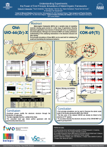
Poster created for the 2015 IAP meeting on September 11th, 2015 in Hasselt, Belgium.
Metal-Organic Frameworks (MOFs) are a versatile class of crystalline materials showing great promise in a wide range of applications. Recently, light-based applications, with a focus on luminescence and photo-catalysis, have become of interest. Although new luminescent MOFs are readily synthesized, a fundamental understanding of the underlying mechanisms in the electronic structure is often lacking.
First principles, or ab initio simulations of these MOFs can be used both for validating the experimentally proposed atomistic model of the MOF and for elucidating its luminescent behavior. On this poster, two different MOF-topologies are investigated. In the first case, we consider the well-known UiO-66(Zr) MOF. For this MOF, it is known that functionalization of the linkers modifies its luminescent behavior. As our second case, we consider the very recently created/synthesized COK-69(Ti) MOF. This new MOF is both flexible and luminescent, making it of interest for various applications.
In our work on the UiO-66, we made use of the primitive unit cell, which contains only a single node and six linker molecules. This cell still contains about 120 atoms (in contrast to about 480 atoms for the conventional cubic cell) making it a rather large system from the point of view of ab initio calculations. The relation between this primitive unit cell and the conventional cubic cell is indicated by comparison to the diamond primitive and cubic cell (top left corner).
The functionalized versions of this MOF were created by manually replacing some of the H atoms of the BDC-linker (benzene-1,4-dicarboxylic acid) by the functional group of interest (OH or SH) and then optimizing the entire structure.
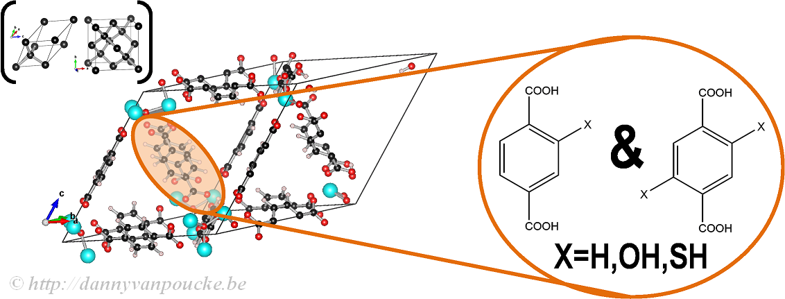
Ball-and-stick model of a primitive unit cell of UiO-66(Zr). Linker functionalization is indicated on the right. Primitive and conventional unit cells for diamond are given as reference.
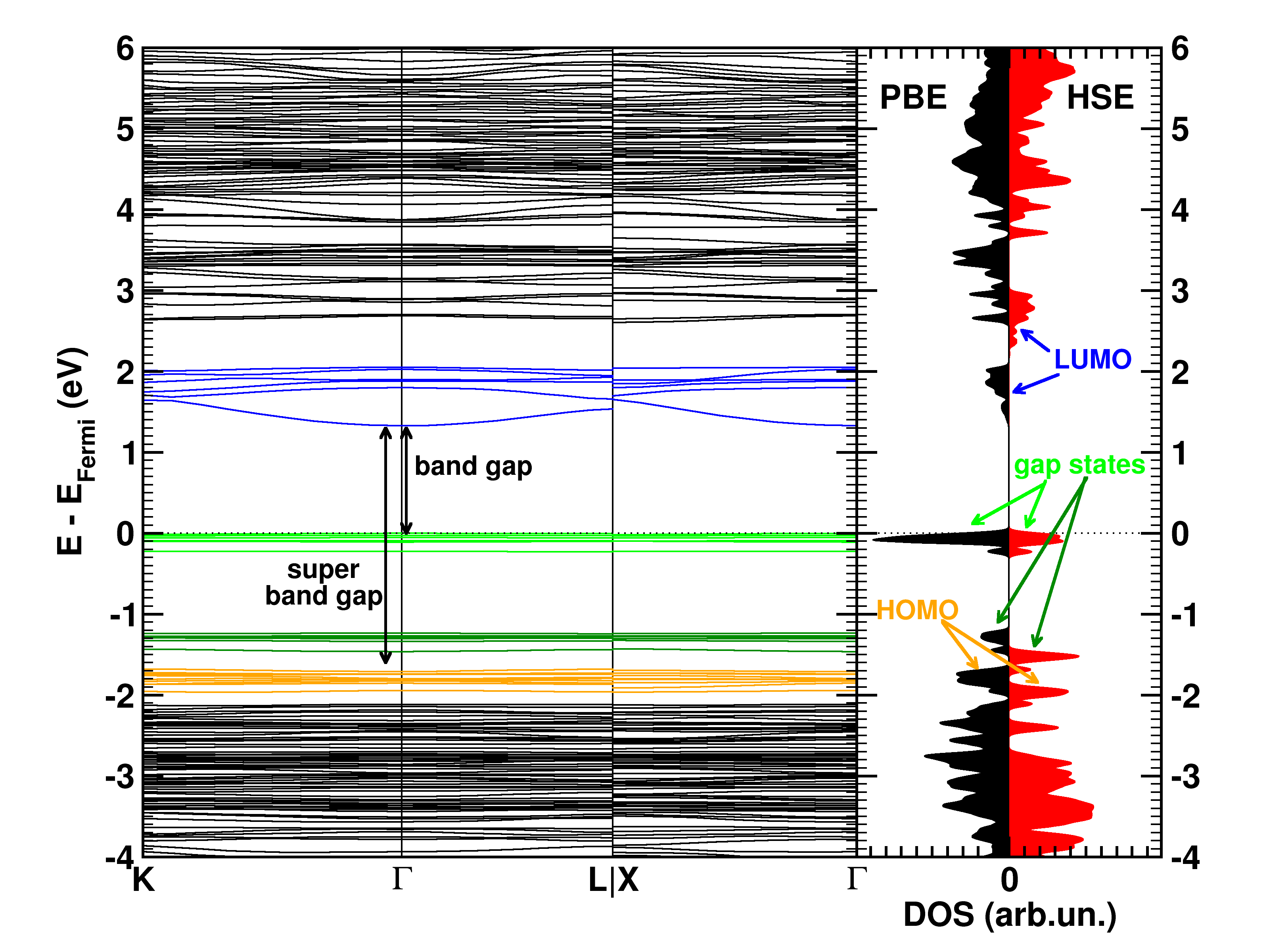
The calculated electronic band structure (left) and density of states (right) of the double SH-functionalized UiO-66(Zr). The conduction band is colored in blue, while the gap states related to the functional groups are colored green. The “old” valence band is colored yellow. This picture is a modified version of the published one.(Ref 1)
Starting from the optimized geometrical structures, the electronic structure is investigated. Taking three high-symmetry lines of the first Brillouin zone, the band structure was generated for all the functionalized MOFs.
The first aspect that drew my attention was the fact that the bottom conduction bands (indicated in blue) remained unchanged while part of the top of the valence band (indicated in green) splits off and moved upward into the band gap. At this point, nomenclature also becomes a bit of a problem. In a doped semi-conductor, the green bands would be called gap states, which would mean that the band gap of the host-material remains unchanged (which is actually also the case here, the distance between the yellow valence band and the blue conduction band is exactly the same for all functionalized UiO-66(Zr) systems we investigated). However, unlike those semiconductors, these gap states are entirely filled, and contain a significant electron occupation (in doped semi-conductors, these states often appear due to ppm doping). Because of this, they take the role of the valence band leading to a measured band gap equal to the distance between the top green bands and the conduction band (blue). So we end up with two band gaps. To have a clear link with experiments on MOFs, we will call the latter the band gap, while we will call the distance between the yellow and blue bands the “super band gap” (super, to indicate that we go beyond the size of the band gap, but it can still be considered a band gap. If that were not the case, we should call it the “supra band gap”).
The discussion of the super band gap can be rather short: it remains unchanged from the value of the unfunctionalized UiO-66(Zr): roughly 4 eV. In contrast, the band gap depends on both the functional group, and the number of functional groups present on each linker. In case of the double SH-functionalized linkers, each functional group leads to a gap state that is being split of from the valence band (cf. two green bands in the right picture).
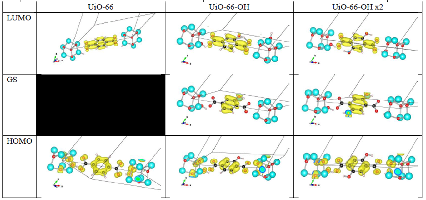
Orbital character of gap states, and valence and conduction bands for OH functionalized linkers in UiO-66(Zr).
Analysis of the orbital character shows that the splitting of the valence band can be taken quite literal. Where the valence band (or HOMO if you use molecular terminology) of the unfunctionalized UiO-66(Zr) mainly consists of the π-orbital of the BDC linker, this orbital is split upon functionalization. The conduction band orbital (or LUMO) on the other hand is barely modified.
Because LDA and GGA functionals are well-known to underestimate the experimental band gaps (even though the band structure is qualitatively well represented), we have also used a hybrid functional (HSE06, which was developed for solids) to calculate the band gap, and as expected, we find that the qualitative picture of the electron density of states (DOS) is retained, and the resulting calculated band gap is in perfect agreement with the experimentally measured values (experiments performed by Kevin Hendrickx of the Centre for Ordered Materials, Organometallics and Catalysis at Ghent University).
In conclusion, our ab initio calculations have shown us that functionalization of the linkers leads to a splitting of the valence band and the creation of a gap state, and that the band gap can be predicted with great accuracy for these materials.
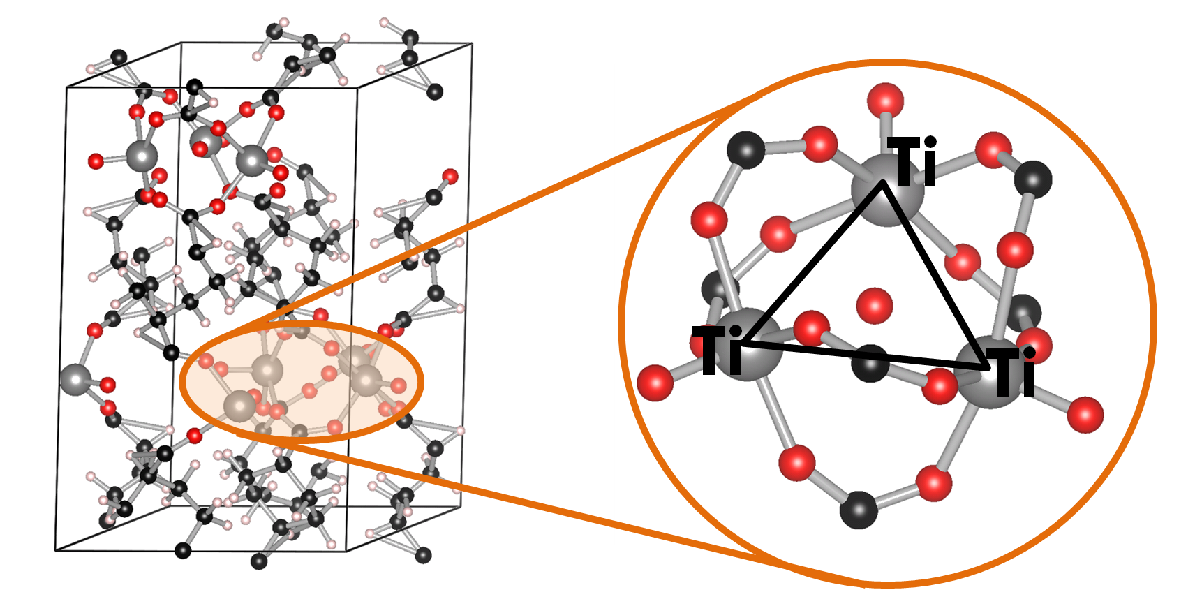
Ball-and-stick model of the COK-69(Ti) MOF. A single triangular Ti cluster is shown in more detail.
The COK-69(Ti) MOF is a newly developed MOF by the Center for Surface Chemistry and Catalysis of the university of Leuven. It is one of the few Ti containing MOFs that have already been synthesized. Because of this, the initial model provided was not sufficiently accurate to perform good electronic structure calculations. The weak point of the model was the uncertainty of the actual structure of the triangular Ti-O clusters. The original model (figure a) was not charge balanced. As a result, the electronic structure of this model showed it to be a metal (or a very narrow band gap semiconductor), in clear disagreement with experiment. Charge balance could be obtained in several ways: removal of O atoms, formation of H2O bound to the cluster (e.g. figure c) or the formation of OH groups (e.g. figure b). By investigating different models, we found that the removal of O atoms is highly unfavorable, while the formation of OH groups and a bound H2O molecule are comparable in stability. As a result of the latter observation, it is not unreasonable to assume that under experimental conditions the bound H2O molecule dissociates and lead to the formation of two OH groups, and that this process is also reversed, leading to a constant moving back and forth between the two models.

Schematic representation of possible triangular Ti clusters for the CO-69(Ti) MOF.
Also, the calculated electronic structure for both models is reasonably comparable: similar sized band gaps, and the same character for the valence (mainly O states) and the conduction (mainly Ti states) bands. Making it hard to give preference to one model over the other as being the actual ground state structure of this MOF, without further study.
More interestingly, we found the cluster with three OH groups (cf. figure d) to be most stable. In such a model, two of the Ti atoms should have an oxidation number of 4, while one has an oxidation number of 3. Looking into the electronic structure of this specific model of the COK-69 shows some amazing features. Firstly, the band gap is much reduced to about the size associated with a semiconductor, and secondly, the states of the Ti3+ atom show a valence to conduction transition of 3.2 eV, which roughly coincides with the blue color obtained for the irradiated COK-69 MOF.
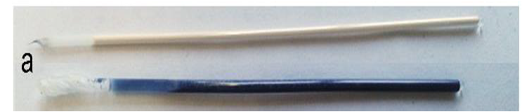
Two samples of the COK-69(Ti) MOF. The normal COK-69 at the top, and the irradiated COK-69 MOF at the bottom. Figure taken from Ref 2.
Ti3+ centers are known to provide a blue color in other materials, and it is now also shown to be the case for this MOF. In addition, experiments on the irradiated COK-69 MOF also showed that no more than 1/3 of the Ti atoms could be Ti3+, which is also the maximum indicated by our model (one Ti per Ti-cluster).
Another interesting bonus provided by this last model is from the theoretical perspective. Due to the symmetry of the cluster and the strong correlation of the Ti-d states, standard DFT is not able to differentiate between the Ti4+ and Ti3+ atoms. As such, the atomic charge is the same for all. By adding an additional Hubbard U potential on the Ti-d states (the so-called DFT+U approach) it is possible to differentiate between the different Ti oxidation states, as is shown by the nice bifurcation diagram.
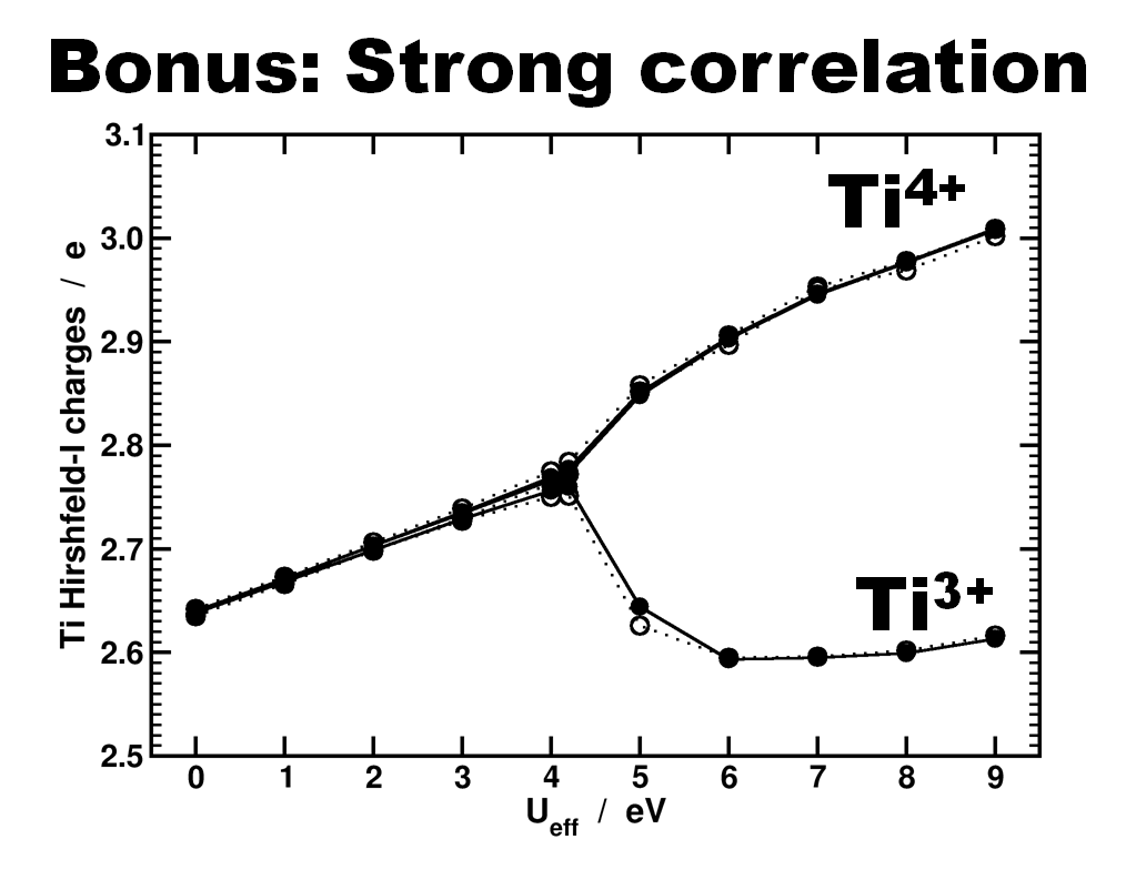
Differentiation of Ti species as function of the U value used in a DFT+U approach. Atomic charges are calculated using the Hirshfeld-I partitioning scheme[3]. Figure taken from Ref 2.
In conclusion, our ab initio calculations allowed us to build a more accurate model of the COK-69 MOF and provide a model for the irradiated COK-69 MOF. In case of the latter, the calculated electronic structure can be used to elucidate the blue color of the irradiated COK-69.
[1] “Understanding intrinsic light absorption properties of UiO-66 frameworks”, K. Hendrickx, D.E.P. Vanpoucke, K. Leus, et al. Inorganic Chemistry (in revision)
[2] “A Flexible Photoactive Titanium MOF based on a [TiIV3(µ3-O)O2(COO)6]-Cluster”, B. Beuken, F. Vermoortele, D.E.P. Vanpoucke, et al. Angewandte Chemie (accepted)
[3] D.E.P. Vanpoucke, P. Bultinck, and I. Van Driessche, J. Comput. Chem. 34 405-417 (2013) & J. Comput. Chem. 34 422-427 (2013)
Aug 29 2015
In the previous fortran tutorials, we learned the initial aspects of object oriented programming (OOP) in fortran 2003. And even though our agent-based opinion-dynamics-code is rather simple, it can quickly take several minutes for a single run of the program to finish. Two tools which quickly become of interest for codes that need more than a few minutes to run are: (1) a progress bar, to track the advance of the “slow” part of the code and prevent you from killing the program 5 seconds before it is to finish, and (2) a timer, allowing you to calculate the time needed to complete certain sections of code, and possibly make predictions of the expected total time of execution.
In this tutorial, we will focus on the progress bar. Since our (hypothetical) code is intended to run on High-Performance Computing (HPC) systems and is written in the fortran language, there generally is no (or no easy) access to GUI’s. So we need our progress bar class to run in a command line user interface. Furthermore, because it is such a widely useful tool we want to build it into a (shared) library (or dll in windows).
What do we want out of our progress bar? It needs to be easy to use, flexible and smart enough to work nicely even for a lazy user. The output it should provide is formatted as follows: <string> <% progress> <text progress bar>, where the string is a custom character string provided by the user, while ‘%progress’ and ‘text progress bar’ both show the progress. The first shows the progress as an updating number (fine grained), while the second shows it visually as a growing bar (coarse grained).
- type, public :: TProgressBar
- private
- logical :: init
- logical :: running
- logical :: done
- character(len=255) :: message
- character(len=30) :: progressString
- character(len=20) :: bar
- real :: progress
- contains
- private
- procedure,pass(this),public :: initialize
- procedure,pass(this),public :: reset
- procedure,pass(this),public :: run
- procedure,pass(this),private:: printbar
- procedure,pass(this),private:: updateBar
- end type TProgressBar
All properties of the class are private (data hiding), and only 3 procedures are available to the user: initialize, run and reset. The procedures, printbar and updatebar are private, because we intend the class to be smart enough to decide if a new print and/or update is required. The reset procedure is intended to reset all properties of the class. Although one might consider to make this procedure private as well, it may be useful to allow the user to reset a progress bar in mid progress.(The same goes for the initialize procedure.)
- subroutine run(this,pct,Ix,msg)
- class(TProgressBar) :: this
- real::pct
- integer, intent(in), optional :: Ix
- character(len=*),intent(in),optional :: msg
-
- if (.not. this%init) call this%initialize(msg)
- if (.not. this%done) then
- this%running=.true.
- this%progress=pct
- call this%updateBar(Ix)
- call this%printbar()
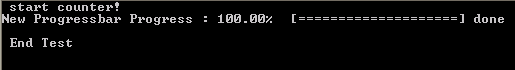
- if (abs(pct-100.0)<1.0E-6) then
- this%done=.true.
- write(*,'(A6)') "] done"
- end if
- end if
-
- end subroutine run
In practice, the run procedure is the heart of the class, and the only procedure needed in most applications. It takes 3 parameters: The progress (pct), the number of digits to print of pct (Ix),and the <string> message (msg). The later two parameters are even optional, since msg may already have been provided if the initialize procedure was called by the user. If the class was not yet initialized it will be done at the start of the procedure. And while the progress bar has not yet reached 100% (within 1 millionth of a %) updates and prints of the bar are performed. Using a set of Boolean properties (init, running, done), the class keeps track of its status. The update and print procedures just do this: update the progress bar data and print the progress bar. To print the progress bar time and time again on the same line, we need to make use of the carriage return character (character 13 of the ASCII table):
write(*,trim(fm), advance='NO') achar(13), trim(this%message),trim(adjustl(this%progressString)),'%','[',trim(adjustl(this%bar))
The advance=’NO‘ option prevents the write statement to move to the next line. This can sometimes have the unwanted side-effect that the write statement above does not appear on the screen. To force this, we can use the fortran 2003 statement flush(OUTPUT_UNIT), where “OUTPUT_UNIT” is a constant defined in the intrinsic fortran 2003 module iso_fortran_env. For older versions of fortran, several compilers provided a (non standard) flush subroutine that could be called to perform the same action. As such, we now have our class ready to be used. The only thing left to do is to turn it into a dll or shared library.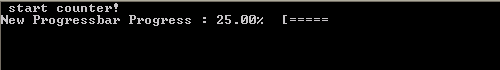
There are two types of libraries: static and dynamic.
Static libraries are used to provide access to functions/subroutines at compile time to the library user. These functions/subroutines are then included in the executable that is being build. In linux environments these will have the extension “.a”, with the .a referring to archive. In a windows environment the extension is “.lib”, for library.
Dynamic libraries are used to provide access to functions/subroutines at run time. In contrast to static libraries, the functions are not included in the executable, making it smaller in size. In linux environments these will have the extension “.so”, with the .so referring to shared object. In a windows environment the extension is “.dll”, for dynamically linked library.
In contrast to C/C++, there is relatively little information to be found on the implementation and use of libraries in fortran. This may be the reason why many available fortran-“libraries” are not really libraries, in the sense meant here. Instead they are just one or more files of fortran code shared by their author(s), and there is nothing wrong with that. These files can then be compiled and used as any other module file.
So how do we create a library from our Progressbar class? Standard examples start from a set of procedures one wants to put in a library. These procedures are put into a .f or .f90 file. Although they are not put into a module (probably due to the idea of having compatibility with fortran 77) which is required for our class, this is not really an issue. The same goes for the .f03 or .f2003 extension for our file containing a fortran 2003 class. To have access to our class and its procedures in our test program, we just need to add the use progressbarsmodule clause. This is because our procedures and class are incorporated in a module (in contrast to the standard examples). Some of the examples I found online also include compiler dependent pragmas to export and import procedures from a dll. Since I am using gfortran+CB for development, and ifort for creating production code, I prefer to avoid such approaches since it hampers workflow and introduces another possible source of bugs.
The compiler setups I present below should not be considered perfect, exhaustive or fool-proof, they are just the ones that work fine for me. I am, however, always very interested in hearing other approaches and fixes in the comments.
The windows approach is very easy. We let Code::Blocks do all the hard work.
Creating the dll : Start a new project, and select the option “Fortran DLL“. Follow the instructions, which are similar to the setup of a standard fortran executable. Modify/replace/add the fortran source you wish to include into your library and build your code (you can not run it since it is a library).
Creating a user program : The program in which you will be using the dll is setup in the usual way. And to get the compilation running smoothly the following steps are required:
The entire setup is the same as for the shared library. This time, however, choose the “Fortran Library” option instead of Fortran dll. As the static library is included in the executable, there is no need to ship it with the executable, as is the case for the dll.
For the unix approach we will be working on the command line, using the intel compiler, since this compiler is often installed at HPC infrastructures.
After having created the appropriate fortran files you wish to include in your library (in our example this is always a single file: PBar.f03, but for multiple files you just need to replace PBar.f03 with the list of files of interest.)
ifort -fpic -c -free -Tf Pbar.f03
Where -fpic tells the compiler to generate position independent code, typical for use in a shared object/library, while -c tells the compiler to create an object file. The -free and -Tf compiler options are there to convince the compiler that the f03 file is actual fortran code to compile and that it is free format.
ar rc PBarlib.a PBar.oifort TestProgram.f90 PBarlib.a -o TestProgram.exe
Note that also here the .mod file of our Progressbarsmodule needs to be present for the compilation to be successful.
For the shared library the approach does not differ that much.
ifort -fpic -c -free -Tf Pbar.f03
In this case the fpic option is not optional in contrast to the static library above. The other options are the same as above.
ifort -shared PBar.o -o libPBar.so
The compiler option -shared creates a shared library, while the -o option allows us to set the name of the library.
ifort TestProgram.f90 libPBar.so -o TestProgram.exe
Note that also here the .mod file of our Progressbarsmodule needs to be present for the compilation to be successful. To run the program you also need to add the location of the library file libPBar.so to the environment variable LD_LIBRARY_PATH
HPC systems may perform extensive buffering of data before output, to increase the efficiency of the machine (disk-writes are the slowest memory access option)…and as a result this can sometimes overrule our flush command. The progressbar in turn will not show much progress until it is actually finished, at which point the entire bar will be shown at once. There are options to force the infrastructure not to use this buffering (and the system administrators in general will not appreciate this), for example by setting the compiler flag -assume nobuffered_stdout. So the best solution for HPC applications will be the construction of a slightly modified progress bar, where the carriage return is not used.
Special thanks also to the people of stack-exchange for clarifying some of the issues with the modules.
Source files for the class and test-program can be downloaded here.


